
Kia EV6: Battery Control System (Standard) / Specification
Kia EV6 (CV/CV1A) 2022-2026 Workshop Manual / Battery Control System (Standard) / Specification
Contents:
Service Data
| Service Data |
| Electric Power Conversion System |
Low Voltage (12 V) Battery
|
Item |
Specification |
|
Type |
eAGM60L-DIN |
|
Capacity [20HR/5HR] (AH) |
60 / 48 |
|
Cold cranking amperage (A) |
500 |
|
Reserve capacity (Min) |
100 |
|
Specific gravity |
1.30 - 1.32 [25°C (77°F)] |
|
Voltage (V) |
12 |
Battery Sensor
|
Item |
Specification |
|
Rated voltage (V) |
12 - 14 |
|
Operating voltage (V) |
6 - 18 |
|
Operating temperature [°C (°F)] |
-40 to 105 (-40 to 221) |
|
Parasitic current (uA) |
Maximum 300 |
Inverter Assembly (4WD)
|
Item |
Specification |
|
Input voltage (V) |
452.5 - 778.3 |
|
Operating voltage (V) |
9 - 16 |
|
Continuous current (A) |
75 (@20 min.) |
|
Maximum ampere (A) |
190 (@15 sec.) |
Multi Inverter Assembly
|
Item |
Specification |
|
Input voltage (V) |
452.5 - 778.3 |
|
Operating voltage (V) |
9 - 16 |
|
Continuous current (A) |
180 (@20 min.) |
|
Maximum ampere (A) |
245 (@15 sec.) |
| High Voltage Battery Control System |
Battery Management Unit (BMU)
| Item |
Specification |
|
| Operating voltage (V) |
9 - 16 |
|
| Operating temperature [°C (°F)] |
-35 to 75 (-31 to 167) |
|
| Insulated resistance (MΩ) |
10 (at 2 kV) |
|
| Parasitic current |
Low voltage (mA) |
1 or below |
|
High voltage (uA) |
100 or below |
|
Cell Monitoring Unit (CMU)
|
Item |
Specification |
|
Operating voltage (V) |
9 - 65 (14 cells) |
|
Operating temperature [°C (°F)] |
-35 to 75 (-31 to 167) |
|
Insulated resistance (MΩ) |
10 (at 2 kV) |
Main Fuse
|
Item |
Specification |
|
Resistance (Ω) |
1.0 or below [20°C (68°F)] |
| Power Relay Assembly (PRA) |
Battery Current Sensor
|
High Current (A) |
Output Voltage (V) |
|
-750 (Charge) |
0.5 |
|
0 |
2.5 |
|
750 (Discharge) |
4.5 |
|
Low Current (A) |
Output Voltage (V) |
|
-75 |
0.5 |
|
0 |
2.5 |
|
75 |
4.5 |
Main Relay
|
Item |
Specification |
|
Rated voltage (V) |
12 |
|
Operating voltage (V) |
Maximum 9 |
|
Coil resistance (Ω) |
21.6 - 26.4 [20°C (68°F)] |
Pre-Charge Relay
|
Item |
Specification |
|
Type |
Mechanical relay |
|
Rated voltage (V) |
12 |
|
Coil resistance (Ω) |
92.7 - 113.3 [20°C (68°F)] |
Voltage & Temperature Sensing Wiring
| Temperature |
Resistance Value (kΩ) |
Tolerance (%) |
|
|
°C |
°F |
||
|
-40 |
-40 |
214.8 |
-0.7 to 0.7 |
|
-30 |
-22 |
122 |
-0.7 to 0.7 |
|
-20 |
-4 |
72.04 |
-0.6 to 0.6 |
|
-10 |
14 |
44.09 |
-0.6 to 0.6 |
|
0 |
32 |
27.86 |
-0.5 to 0.5 |
|
10 |
50 |
18.13 |
-0.4 to 0.4 |
|
20 |
68 |
12.12 |
-0.4 to 0.4 |
|
30 |
86 |
8.3 |
-0.4 to 0.4 |
|
40 |
104 |
5.81 |
-0.5 to 0.5 |
|
50 |
122 |
4.1 |
-0.6 to 0.6 |
|
60 |
140 |
3.01 |
-0.8 to 0.8 |
|
70 |
158 |
2.23 |
-0.9 to 0.9 |
| High Voltage Battery System |
Battery System Assembly (BSA)
|
Item |
Specification |
|
Rated capacity (Ah) |
120.6 |
|
Rated voltage (V) |
523 |
|
Rated energy (kWh) |
63 |
|
Cell capacity (Ah) |
60.3 |
|
Composition |
144 cells (24 modules) |
| High Voltage Charging System |
In Cable Control Box (ICCB)
|
Item |
Specification |
|
Rated voltage (V) |
120 - 230 |
|
Rated current (A) |
6, 8, 10, 12 (Variable Settings) |
Integrated Charging Control Unit (ICCU)
| Item |
Specification |
|
| Function |
On-Board Charger (OBC) + Low Voltage DC/DC Converter (LDC) |
|
| OBC system specification |
Capacity (kW) |
10.9 |
|
Input voltage (V) |
AC 70 - 285 |
|
|
Output voltage (V) |
DC 360 - 845 |
|
|
Input current (A) |
Maximum 48 |
|
| LDC system specification |
Maximum capacity (kW) |
2.567 |
|
Input voltage (V) |
DC 288 - 845 |
|
|
Output voltage (V) |
7 - 16 |
|
|
Ampere (A) |
170 |
|
| Cooling |
Cooling type |
Water cooling |
|
Operating temperature [°C (°F)] |
-40 to 85 (-40 to 185) |
|
Vehicle Charge Management System (VCMS)
|
Item |
Specification |
|
Rated voltage (V) |
DC 11 - 13 |
|
Operating voltage (V) |
DC 9 - 16 |
|
Operating temperature [°C (°F)] |
-30 to 85 (-22 to 185) |
|
Parasitic current (mA) |
Maximum 1.0 (Power off Mode) |
Tightening Torque
| Tightening Torque |
Electric Power Conversion System
Low Voltage (12 V) Battery
|
Item |
N·m |
kgf·m |
lb·ft |
lb·in |
|
Low voltage (12 V) battery ( - ) terminal |
7.8 - 9.8 |
0.8 - 1.0 |
5.8 - 7.2 |
- |
|
Low voltage (12 V) battery ( + ) terminal |
7.8 - 9.8 |
0.8 - 1.0 |
5.8 - 7.2 |
- |
|
Low voltage (12 V) battery clamp |
9.8 - 13.7 |
1.0 - 1.4 |
7.2 - 10.1 |
- |
|
Low voltage (12 V) battery tray |
9.8 - 13.7 |
1.0 - 1.4 |
7.2 - 10.1 |
- |
Battery Sensor
|
Item |
N·m |
kgf·m |
lb·ft |
lb·in |
|
Low voltage (12 V) battery ( - ) terminal |
7.8 - 9.8 |
0.8 - 1.0 |
5.8 - 7.2 |
- |
|
Battery sensor |
26.5 - 32.4 |
2.7 - 3.3 |
19.5 - 23.9 |
- |
Inverter Assembly (4WD)
|
Item |
N·m |
kgf·m |
lb·ft |
lb·in |
|
Inverter assembly |
3.9 - 5.9 |
0.4 - 0.6 |
2.9 - 4.3 |
34.7 - 52.1 |
Multi Inverter Assembly
|
Item |
N·m |
kgf·m |
lb·ft |
lb·in |
|
Wiring protector |
6.9 - 9.8 |
0.7 - 1.0 |
5.1 - 7.2 |
- |
|
Ground cable |
7.8 - 9.8 |
0.8 - 1.0 |
5.8 - 7.2 |
- |
|
Multi inverter assembly |
3.9 - 5.9 |
0.4 - 0.6 |
2.9 - 4.3 |
34.7 - 52.1 |
High Voltage Battery Control System
Battery Management Unit (BMU)
| Item |
N·m |
kgf·m |
lb·ft |
lb·in |
|
| Battery Management Unit (BMU) service cover |
1st |
8.8 |
0.9 |
6.5 |
- |
|
2nd |
10.8 |
1.1 |
8.0 |
- |
|
| BMU |
7.8 - 11.8 |
0.8 - 1.2 |
5.8 - 8.7 |
- |
|
Cell Monitoring Unit (CMU)
| Item |
N·m |
kgf·m |
lb·ft |
lb·in |
| Main fuse ( - ) bus bar |
7.8 - 11.8 |
0.8 - 1.2 |
5.8 - 8.7 |
- |
|
Front junction box ↔ Power Relay Assembly (PRA) bus bar |
7.8 - 11.8 |
0.8 - 1.2 |
5.8 - 8.7 |
- |
|
Cell Monitoring Unit (CMU) |
7.8 - 11.8 |
0.8 - 1.2 |
5.8 - 8.7 |
- |
Main Fuse
|
Item |
N·m |
kgf·m |
lb·ft |
lb·in |
|
Bus bar |
7.8 - 11.8 |
0.8 - 1.2 |
5.8 - 8.7 |
- |
|
Main Fuse |
15.7 - 16.7 |
1.6 - 1.7 |
11.6 - 12.3 |
- |
|
Main fuse housing |
7.8 - 11.8 |
0.8 - 1.2 |
5.8 - 8.7 |
- |
Power Relay Assembly (PRA)
| Item |
N·m |
kgf·m |
lb·ft |
lb·in |
|
| Front junction box ↔ Power Relay Assembly (PRA) bus bar |
7.8 - 11.8 |
0.8 - 1.2 |
5.8 - 8.7 |
- |
|
| Integrated Charging Control Unit (ICCU) connector |
7.8 - 11.8 |
0.8 - 1.2 |
5.8 - 8.7 |
- |
|
| PRA ↔ Battery Module Assembly (BMA) bus bar |
7.8 - 11.8 |
0.8 - 1.2 |
5.8 - 8.7 |
- |
|
| Battery ( + ) bus bar |
7.8 - 11.8 |
0.8 - 1.2 |
5.8 - 8.7 |
- |
|
| Inverter ( + ), ( - ) bus bar |
7.8 - 11.8 |
0.8 - 1.2 |
5.8 - 8.7 |
- |
|
| Power Relay Assembly (PRA) |
1st |
8.8 |
0.9 |
6.5 |
- |
|
2nd |
10.8 |
1.1 |
8.0 |
- |
|
Voltage & Temperature Sensing Wiring
|
Item |
N·m |
kgf·m |
lb·ft |
lb·in |
|
Main fuse ( - ) bus bar |
7.8 - 11.8 |
0.8 - 1.2 |
5.8 - 8.7 |
- |
|
Front junction box ↔ Power Relay Assembly (PRA) bus bar |
7.8 - 11.8 |
0.8 - 1.2 |
5.8 - 8.7 |
- |
High Voltage Battery System
Battery Module Assembly (BMA)
| Item |
N·m |
kgf·m |
lb·ft |
lb·in |
| High voltage battery module disassembly jig |
4.9 - 6.9 |
0.5 - 0.7 |
3.6 - 5.1 |
43.4 - 60.8 |
| Battery Module Assembly (BMA) |
7.8 - 11.8 |
0.8 - 1.2 |
5.8 - 8.7 |
- |
Battery System Assembly (BSA)
|
Item |
N·m |
kgf·m |
lb·ft |
lb·in |
|
Battery System Assembly (BSA) through bolt |
68.6 - 88.3 |
7.0 - 9.0 |
50.6 - 65.1 |
- |
|
BSA bolt |
117.7 - 137.3 |
12.0 - 14.0 |
86.8 - 101.3 |
- |
|
BSA ground cable |
7.8 - 11.8 |
0.8 - 1.2 |
5.8 - 8.7 |
- |
Case
| Item |
N·m |
kgf·m |
lb·ft |
lb·in |
|
| High voltage battery system upper case bolt |
103.0 - 154.9 |
10.5 - 15.8 |
75.9 - 114.3 |
- |
|
| Upper Case |
1st |
8.8 |
0.9 |
6.5 |
- |
|
2nd |
10.8 |
1.1 |
8.0 |
- |
|
| Front high voltage junction box connector assembly |
1st |
8.8 |
0.9 |
6.5 |
- |
|
2nd |
10.8 |
1.1 |
8.0 |
- |
|
| Integrated Charging Control Unit (ICCU) connector service cover |
7.8 - 11.8 |
0.8 - 1.2 |
5.8 - 8.7 |
- |
|
| ICCU connector assembly |
1st |
8.8 |
0.9 |
6.5 |
- |
|
2nd |
10.8 |
1.1 |
8.0 |
- |
|
| Rear high voltage junction box connector assembly |
1st |
8.8 |
0.9 |
6.5 |
- |
|
2nd |
10.8 |
1.1 |
8.0 |
- |
|
| Battery Management Unit (BMU) connector assembly |
1st |
8.8 |
0.9 |
6.5 |
- |
|
2nd |
10.8 |
1.1 |
8.0 |
- |
|
Sub Battery Pack Assembly (Sub-BPA)
| Item |
N·m |
kgf·m |
lb·ft |
lb·in |
|
| Main fuse ( - ) bus bar |
7.8 - 11.8 |
0.8 - 1.2 |
5.8 - 8.7 |
- |
|
| Front junction box ↔ Power Relay Assembly (PRA) bus bar |
7.8 - 11.8 |
0.8 - 1.2 |
5.8 - 8.7 |
- |
|
| PRA ↔ Battery Module Assembly (BMA) bus bar |
7.8 - 11.8 |
0.8 - 1.2 |
5.8 - 8.7 |
- |
|
| Sub Battery Pack Assembly (Sub-BPA) bus bar |
7.8 - 11.8 |
0.8 - 1.2 |
5.8 - 8.7 |
- |
|
| Main fuse ( + ) bus bar |
7.8 - 11.8 |
0.8 - 1.2 |
5.8 - 8.7 |
- |
|
| BMA bus bar |
7.8 - 11.8 |
0.8 - 1.2 |
5.8 - 8.7 |
- |
|
| Mounting bracket |
1st |
8.8 |
0.9 |
6.5 |
- |
|
2nd |
10.8 |
1.1 |
8.0 |
- |
|
| Sub Battery Pack Assembly (Sub-BPA) |
1st |
8.8 |
0.9 |
6.5 |
- |
|
2nd |
10.8 |
1.1 |
8.0 |
- |
|
High Voltage Charging System
Charge Junction Box Unit
|
Item |
N·m |
kgf·m |
lb·ft |
lb·in |
|
Charge junction box unit |
9.8 - 11.8 |
1.0 - 1.2 |
7.2 - 8.7 |
- |
Charger Inlet Assembly
|
Item |
N·m |
kgf·m |
lb·ft |
lb·in |
|
Quick charge connector service cover |
4.9 - 7.8 |
0.5 - 0.8 |
3.6 - 5.8 |
43.4 - 69.4 |
|
Quick charge connector |
9.3 - 10.3 |
0.95 - 1.05 |
6.9 - 7.6 |
- |
|
Ground cable |
10.8 - 13.7 |
1.1 - 1.4 |
8.0 - 10.1 |
- |
|
charger inlet assembly protector |
4.9 - 7.8 |
0.5 - 0.8 |
3.6 - 5.8 |
43.4 - 69.4 |
|
charger inlet assembly |
6.9 -9.8 |
0.7 - 1.0 |
5.1 - 7.2 |
- |
Integrated Charging Control Unit (ICCU)
|
Item |
N·m |
kgf·m |
lb·ft |
lb·in |
|
Low Voltage DC/DC Converter (LDC) ( - ) cable |
7.8 - 9.8 |
0.8 - 1.0 |
5.8 - 7.2 |
- |
|
LDC ( + ) cable |
7.8 - 9.8 |
0.8 - 1.0 |
5.8 - 7.2 |
- |
|
Integrated Charging Control Unit (ICCU) |
19.6 - 23.5 |
2.0 - 2.4 |
14.5 - 17.4 |
- |
|
ICCU pad |
3.9 - 5.9 |
0.4 - 0.6 |
2.9 - 4.3 |
34.7 - 52.1 |
|
ICCU fuse service cover |
7.8 - 11.8 |
0.8 - 1.2 |
5.8 - 8.7 |
- |
|
ICCU fuse cover |
2.5 - 3.3 |
0.26 - 0.34 |
1.9 - 2.5 |
22.6 - 29.5 |
|
ICCU fuse |
4.4 - 5.4 |
0.45 - 0.55 |
3.3 - 4.0 |
39.1 - 47.7 |
Vehicle Charge Management System (VCMS)
|
Item |
N·m |
kgf·m |
lb·ft |
lb·in |
|
Vehicle Charge Management System (VCMS) bracket |
6.9 - 9.8 |
0.7 - 1.0 |
5.1 - 7.2 |
- |
|
VCMS |
9.8 - 11.8 |
1.0 - 1.2 |
7.2 - 8.7 |
- |
High Voltage Distributing System
Front High Voltage Junction Box (2WD)
|
Item |
N·m |
kgf·m |
lb·ft |
lb·in |
|
Front high voltage junction box |
4.9 - 7.8 |
0.5 - 0.8 |
3.6 - 5.8 |
43.4 - 69.4 |
Front High Voltage Junction Box (4WD)
|
Item |
N·m |
kgf·m |
lb·ft |
lb·in |
|
Wiring protector |
6.9 - 9.8 |
0.7 - 1.0 |
5.1 - 7.2 |
- |
|
High voltage junction box service cover |
3.9 - 5.9 |
0.4 - 0.6 |
2.9 - 4.3 |
34.7 - 52.1 |
|
Front high voltage junction box ground bolt |
6.9 - 9.8 |
0.7 - 1.0 |
5.1 - 7.2 |
- |
|
Front high voltage junction box |
6.9 - 9.8 |
0.7 - 1.0 |
5.1 - 7.2 |
- |
Rear High Voltage Junction Box
| Item |
N·m |
kgf·m |
lb·ft |
lb·in |
|
| Rear high voltage junction box bolt |
15.7 - 23.5 |
1.6 - 2.4 |
11.6 - 17.4 |
- |
|
| High voltage cable |
15.7 - 23.5 |
1.6 - 2.4 |
11.6 - 17.4 |
- |
|
| High voltage junction box service cover |
3.9 - 5.9 |
0.4 - 0.6 |
2.9 - 4.3 |
34.7 - 52.1 |
|
| Rear high voltage junction box and inverter bolt |
6.9 - 9.8 |
0.7 - 1.0 |
5.1 - 7.2 |
- |
|
| Rear high voltage junction box |
Bolt |
15.7 - 23.5 |
1.6 - 2.4 |
11.6 - 17.4 |
- |
|
Nut |
17.7 - 26.5 |
1.8 - 2.7 |
13.0 - 19.5 |
- |
|


Other information:
Kia EV6 (CV/CV1A) 2022-2026 Workshop Manual: Switching between panels
Figure 1. Infotainment control panel Figure 2. Climate control panel Press the Kia EV6 switchable controller button to activate the desired control panel mode. The selected Kia EV6 control panel icon illuminates and the controller switches to the chosen operating mode.Kia EV6 (CV/CV1A) 2022-2026 Workshop Manual: When the Approach unlock is activated
When approaching the Kia EV6 within approximately 1 ft. (30 cm) of either the driver’s or front passenger’s door while carrying the registered smart key, the exterior door handles automatically extend outward and the doors unlock for convenient entry. At the same time, the hazard warning lights flash twice and the confirmation chime sounds twice, notifying the driver that the Kia EV6 has recognized the smart key and unlocked the vehicle successfully.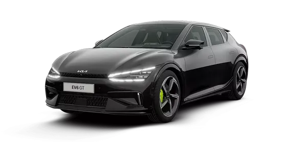
Contents
Categories
- Manuals Home
- Kia EV6 Owners Manual
- Kia EV6 Service Manual
- Questions & Answers
- Video Guides
- Useful Resources
- New on site
- Most important about Kia EV6
- Privacy Policy

Copyright © 2026 Kia EV6 Manuals ⏱ 0.0179