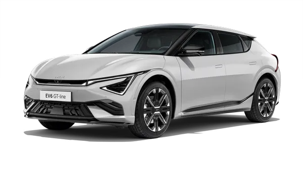
Kia EV6: Battery Control System (Standard) / High Voltage Battery Control System
Contents:
Components and Components Location

1. Main Fuse
2. Voltage & Temperature Sensing
Wiring
3. Battery Management Unit (BMU)
|
4. Power Relay Assembly (PRA)
5. BMU wiring
6.
Cell Monitoring Unit (CMU)
|
Description and Operation
| High Voltage Control System Description |
|
•
|
The high voltage battery control system consists of the Battery Management Unit (BMU), the Cell Monitoring
Unit (CMU) and the Power Relay Assembly (PRA).
|
|
•
|
It controls the SOC, power, fault diagnosis, battery cell balancing and supplying and shutting the power.
Components
|
Function
|
Battery Management Unit (BMU)
|
|
•
|
The BMU manages the entire high voltage battery pack as the central control. It also
controls the high voltage relay (main relay, pre charge relay, etc.) in the battery system and
communicates with other components and controllers in the vehicle.
|
|
•
|
The BMU is installed inside the high voltage battery. It calculates the battery state of
charge (SOC) by measuring the battery voltage and temperature from the Cell Monitoring Unit
(CMU), and this information is sent to the Vehicle Control Unit (VCU) for controlling and
managing the proper SOC range.
|
|
•
|
The information about the SOC is displayed through the CAN communication on the cluster for
the driver to know.
|
|
Cell Monitoring Unit (CMU)
|
|
•
|
The CMU manages the deviation of the voltage between cells, by using the internal cell
balancing device if there is a deviation when measuring the voltage in each cell in the
module.
|
|
•
|
The CMU measures the temperature, voltage and OPD (Overvoltage Protection Device) of the
high voltage battery module, and this data is sent to the BMU.
|
|
Power Relay Assembly (PRA)
|
|
•
|
The PRA connects power to the battery for supplying power to the vehicle and driving the
vehicle.
|
|
•
|
The PRA is intended to supply high voltage power to the system related to vehicle driving.
It also consists of the main relay ( +, - ) for connecting and disconnecting the power, pre
charge relay, pre charge resistor, and the battery current sensor, etc.
|
|
•
|
The PRA protects the circuit from being damaged by the high voltage.
|
|
Main Fuse
|
|
•
|
Instead of a safety plug, a high-capacity main fuse is installed to protect the circuit
against high voltage.
|
|
|
| 1) |
SOC control : It controls to proper range by calculating the SOC
through measuring the voltage, current, and temperature.

|
| 2) |
Battery output control : It maximizes the battery protection,
available power prediction and charge/discharge energy by calculating the input/output energy values according
to system state. It also prevents overcharge/over discharge.
The limit of the high voltage battery output is a function that controls the energy for battery protection
during charging and discharging. The Vehicle Control Unit (VCU) calculates the input/output energy limited
value by receiving a signal from the BMU.
|
•
|
To prevent overcharging, the battery charge is controlled by receiving a signal from the
OPD (Over voltage Protection Device).
|
|
•
|
When charging a battery, the charging current is limited to prevent battery overheating
according to the SOC (State of Charge) value.
|
|
|
| 3) |
Relay control : It supplies and shuts the power off to system
related to high voltage and high voltage system, and prevents safety accidents by shutting the relay off in
case of failure.
The problems are diagnosed during the normal operation of the high voltage and monitored by using the input
information from the temperature, current, and voltage sensors. It also prevents safety accidents by
distinguishing fail-safe levels and controlling the main relay to limit output.
|
| 4) |
Heating control : It maintains the best battery operating
temperature through 3 way valve, Electric Water Pump (EWP) control, PTC heater control (optional).
The EWP facilitates the coolant circulation and controls forced circulation.
The battery temperature is maintained constantly in the winter through PTC heat control.
|
| 5) |
Troubleshooting : Diagnose system faults and classify fail-safe
levels to prevent safety accidents through output restrictions or relay control.
The main relay controls power related to driving the vehicle and other power used in the vehicle. Through
it, the power can also be cut off when overcharged.
|
•
|
SOC : It is the available battery energy, and the discharge ratio compared to the battery
rated capacity. It also means the ratio of current that can be supplied.
|
|
•
|
SOC = (Dischargeable current / Battery rated capacity) X 100%
|
|
|
| High Voltage Control System Logic |


Battery Management Unit (BMU) Specification. Battery Management Unit (BMU) Components and Components Location
Battery Management Unit (BMU) Specification
Item
|
Specification
|
Operating voltage (V)
|
9 - 16
|
Operating temperature [°C (°F)]
|
-35 to 75 (-31 to 167)
|
Insulated resistance (MΩ)
|
10 (at 2 kV)
|
Parasitic current
|
Low voltage (mA)
|
1 or below
|
High voltage (uA)
|
100 or below
|
Battery Management Unit (BMU) Components and Components Location
With Service Cover

1. Service Cover
1-a. Step 1 : 8.8 N·m (0.9 kgf·m,
6.5 lb·ft)
1-a. Step 2 : 10.8 N·m (1.1 kgf·m, 8.0 lb·ft)
|
2. Battery Management Unit (BMU)
2-a. 7.8 - 11.8 N·m
(0.8 - 1.2 kgf·m, 5.8 - 8.7 lb·ft)
|
Without Service Cover

1. Upper Case Bolt
1-a. 103.0 - 154.9 N·m (10.5 -
15.8 kgf·m, 75.9 - 114.3 lb·ft)
2. O-ring
3. Watertight Bracket
3-a. 1st : 8.8 N·m (0.9 kgf·m, 6.5
lb·ft)
3-a. 2nd : 10.8 N·m (1.1 kgf·m, 8.0 lb·ft)
|
4. Upper Case
5. Waterproof Gasket
6. Battery
Management Unit (BMU)
6-a. 7.8 - 11.8 N·m (0.8 - 1.2 kgf·m, 5.8 - 8.7 lb·ft)
|
Battery Management Unit (BMU) Description and Operation
|
•
|
The Battery Management Unit (BMU) is installed inside the high voltage battery. It manages the battery
lifespan, performance and safety.
|
|
•
|
The BMU is important during the charging and discharging of the high voltage battery system that uses a
secondary battery, such as an EV.
|
|
•
|
The BMU receives the voltage, temperature, and current sensor signals from the battery to check the battery
condition. These signals are used to maintain the best battery condition by controlling.
|
Battery Management Unit (BMU) Function
|
•
|
The BMU monitors and diagnoses the battery condition from the voltage, temperature, and current sensor
signals in real time.
|
|
•
|
To prevent the battery when overcharged through the signal from the Overvoltage Protection Device (OPD) in
the high voltage battery, the main relay cuts off.
|
|
•
|
It calculates the battery State of Charge (SOC) by using the input information from the high voltage
battery. This information is sent to the Vehicle Control Unit (VCU) for controlling and managing the proper
SOC range.
|
|
•
|
It checks the degree of aged by the battery deterioration and predicts the replacement time, by using the
input information from the high voltage battery.
|
|
•
|
The coolant is circulated to prevent increasing the battery temperature when a high voltage battery is
charged and discharged. In addition, the cooling fan is working to control the battery heat.

|
Battery Management Unit (BMU) On Vehicle Inspection
|
•
|
When working on the high voltage system, the work should be performed by technicians who have
completed the relevant training. A lack of understanding of the high voltage system can lead to
serious accidents due to electric shock or short circuit.
|
|
•
|
When working on the high voltage system or related components, be sure to observe and be aware of
the "Safety Precautions, Cautions and Warnings". If not, it may cause serious accidents due
to electric shock or short circuit.
|
|
•
|
When working on high voltage system, make sure to check the Personal Protective Equipment (PPE) and
high voltage shut-off procedure.
|
|
|
In the case of the Battery Management Unit (BMU) related fault, inspect the related problem components and
replace the BMU when it is normal.

|
| 1. |
Diagnose the BMU with the KDS. (Refer to DTC guide manual)
|
Refer to the KDS screen for operating conditions and details.
|
|
| 2. |
Remove the BMU service cover (A) after removing the bolts.
Tightening torque
Step 1 : 8.8 N·m (0.9 kgf·m, 6.5 lb·ft)
Step 2 : 10.8 N·m (1.1 kgf·m, 8.0 lb·ft)
|

|
| 3. |
When the BMU failures, inspect or replace it if necessary.
Connector connection state
| (1)
|
Check the BMU connectors (A) connection state.

|
CAN communication line inspection
| (1)
|
Measure the G-CAN line voltage at the POWER ON.
Inspection area : Between D19 (CAN LOW) and vehicle
body ground, and between D20 (CAN HIGH) and vehicle ground.
Specified value (V) : 1.5 - 3.5
|
|
| (2)
|
Measure the G-CAN line terminating resistors.
Inspection area : D19 and D20
Specified value (Ω) : 120
|
|
|
| 4. |
If the BMU is normal, inspect the components related with fault code (DTC).
|
Refer to the DTC guide manual for inspection ways according to the fault code.
|
|
Battery Management Unit (BMU) Removal and Installation
|
•
|
When working on high voltage system, the work should be performed by technicians who have completed
the relevant training. A lack of understanding of the high voltage system can lead to serious
accidents due to electric shock or electric leakage.
|
|
•
|
When working on high voltage system or related components, make sure that you are familiar and
comply with the "Safety Precautions, Cautions and Warnings." If you do not comply with the
instructions, serious accidents due to electric shock or leakage may occur.
|
|
•
|
When working on high voltage system, make sure to check the Personal Protective Equipment (PPE) and
high voltage shut-off procedures.
|
|
With Service Cover
| 1. |
Shut off the high voltage circuit.
(Refer to Battery Control System (Standard) - “High Voltage Shut-off
Procedure”)
|
| 2. |
Remove the Battery Management Unit (BMU) service cover (A) after removing the bolts.
Tightening torque
1st : 8.8 N·m (0.9 kgf·m, 6.5 lb·ft)
2nd : 10.8 N·m (1.1 kgf·m, 8.0 lb·ft)
|
|
| 3. |
Disconnect the BMU connectors (A).
|
| 4. |
Remove the BMU (A) from the service cover after removing the bolt and nuts.
Tightening torque:
7.8 - 11.8 N·m (0.8 - 1.2 kgf·m, 5.8 - 8.7 lb·ft)
|

|
Without Service Cover
| 1. |
Remove the Battery System Assembly (BSA) upper case.
(Refer to High Voltage Battery System - "Case")
|
| 2. |
Disconnect the Battery Management Unit (BMU) connectors (A).

|
| 3. |
Separate the BMU wiring (A).

|
| 4. |
Remove the BMU (A) after removing the bolt and nuts.
Tightening torque:
7.8 - 11.8 N·m (0.8 - 1.2 kgf·m, 5.8 - 8.7 lb·ft)
|

|
|
•
|
When working on the high voltage system, the work should be performed by technicians who have
completed the relevant training. A lack of understanding of the high voltage system can lead to
serious accidents due to electric shock or short circuit.
|
|
•
|
When working on the high voltage system or related components, be sure to observe and be aware of
the "Safety Precautions, Cautions and Warnings". If not, it may cause serious accidents due
to electric shock or short circuit.
|
|
•
|
When working on high voltage system, make sure to check the Personal Protective Equipment (PPE) and
high voltage shut-off procedure.
|
|
| 1. |
Install in the reverse order of removal.
|
•
|
Install the Battery Management Unit (BMU) to the specified torque.
|
|
•
|
If the BMU is dropped, it may cause internal damage. (Do not reuse)
|
|
•
|
Install the service cover after completely removing existing tape on the battery side to
prevent the air leakage.
|
|
•
|
The service cover should be replaced with a new one. (Do not reuse)
|
|
|
| 2. |
Perform the air tightness inspection with the KDS.
(Refer to High Voltage Battery System - "Air Tightness
Inspection")
|
| 3. |
Perform the SOC calibration with the KDS.
(S/W management → Battery Management System (BMS) → SOC Calibration)
|
| 4. |
Perform the SOH reset with the KDS.
(S/W Management → Battery Management System (BMU) → SOH Reset)
|
|
Refer to the KDS screen for operating conditions and details.
|
Cell Monitoring Unit (CMU) Specification. Cell Monitoring Unit (CMU) Components and Components Location
Cell Monitoring Unit (CMU) Specification
Item
|
Specification
|
Operating voltage (V)
|
9 - 65 (14 cells)
|
Operating temperature [°C (°F)]
|
-35 to 75 (-31 to 167)
|
Insulated resistance (MΩ)
|
10 (at 2 kV)
|
Cell Monitoring Unit (CMU) Components and Components Location

1. Upper Case Bolt
1-a. 103.0 - 154.9 N·m (10.5 -
15.8 kgf·m, 75.9 - 114.3 lb·ft)
2. O-Ring
3. Upper Case
3-a. Step 1 : 8.8 N·m (0.9 kgf·m, 6.5
lb·ft)
3-a. Step 2 : 10.8 N·m (1.1 kgf·m, 8.0 lb·ft)
|
4. Waterproof Gasket
5. Cell Monitoring Unit
(CMU)
5-a. 7.8 - 11.8 N·m (0.8 - 1.2 kgf·m, 5.8 - 8.7 lb·ft)
|
Cell Monitoring Unit (CMU) Description and Operation
The Cell Monitoring Unit (CMU) is divided into each battery pack. It is installed in the corresponding module and
manages only the corresponding cells.
Cell Monitoring Unit (CMU) Function
|
•
|
It measures the voltage in each cell, and controls a deviation by using the resistance and the relay that
is the cell balancing device inside the CMU when there is a deviation of voltage between cells. In this
process, the CMU monitors and measures the cell voltage while communicating with the BMU.
|
It is different to the role of the relay and resistance that are installed in the CMU for cell
balancing.
|
–
|
The relay controls the balance of the voltage by delivering more charging capacity to cells
with less capacity when there is a deviation in the voltage between cells.
|
|
–
|
The resistance controls the balance of the voltage by converting the power from a place
with high voltage capacity into heat when there is a deviation in the voltage between cells.
|
|
|
|
•
|
The temperature of each cell is measured using a temperature sensor connected to the battery module and
sent to the BMU to maintain the battery temperature at an optimal level.
|
|
•
|
When the problem happens in the battery due to overcharging, the signal is received from the Overvoltage
Protection Device (OPD) connected to the CMU, and this signal is sent to the BMU to cut the main relay and pre
charge relay connections.
|
|
•
|
The CMU is 6 for standard and 8 for long range. (There is 4 modules in a Sub-BPA, and a CMU controls the 4
modules.)

|
Cell Monitoring Unit (CMU) Terminal Function
| Cell Monitoring Unit (CMU) Connector and Terminal |

Cell Monitoring Unit (CMU)
|
Module
|
Cell Number
|
Terminal
|
In ETM
|
#1
|
1
|
1
|
1 - 14
|
C0 - C1
|
2
|
14 - 2
|
C1 - C2
|
3
|
2 - 15
|
C2 - C3
|
4
|
15 - 3
|
C3 - C4
|
5
|
3 - 16
|
C4 - C5
|
6
|
16 - 4
|
C5 - C6
|
2
|
7
|
17 - 5
|
C7 - C8
|
8
|
5 - 18
|
C8 - C9
|
9
|
18 - 6
|
C9 - C10
|
10
|
6 - 19
|
C10 - C11
|
11
|
19 - 20
|
C11 - C12
|
12
|
20 - 21
|
C12 - C13
|
3
|
13
|
24 - 25
|
C0 - C1
|
14
|
25 - 26
|
C1 - C2
|
15
|
26 - 7
|
C2 - C3
|
16
|
7 - 27
|
C3 - C4
|
17
|
27 - 8
|
C4 - C5
|
18
|
8 - 28
|
C5 - C6
|
4
|
19
|
9 - 29
|
C7 - C8
|
20
|
29 - 10
|
C8 - C9
|
21
|
10 - 30
|
C9 - C10
|
22
|
30 - 11
|
C10 - C11
|
23
|
11 - 31
|
C11 - C12
|
24
|
31 - 12
|
C12 - C13
|
#2
|
5
|
25
|
1 - 14
|
C0 - C1
|
26
|
14 - 2
|
C1 - C2
|
27
|
2 - 15
|
C2 - C3
|
28
|
15 - 3
|
C3 - C4
|
29
|
3 - 16
|
C4 - C5
|
30
|
16 - 4
|
C5 - C6
|
6
|
31
|
17 - 5
|
C7 - C8
|
32
|
5 - 18
|
C8 - C9
|
33
|
18 - 6
|
C9 - C10
|
34
|
6 - 19
|
C10 - C11
|
35
|
19 - 20
|
C11 - C12
|
36
|
20 - 21
|
C12 - C13
|
7
|
37
|
24 - 25
|
C0 - C1
|
38
|
25 - 26
|
C1 - C2
|
39
|
26 - 7
|
C2 - C3
|
40
|
7 - 27
|
C3 - C4
|
41
|
27 - 8
|
C4 - C5
|
42
|
8 - 28
|
C5 - C6
|
8
|
43
|
9 - 29
|
C7 - C8
|
44
|
29 - 10
|
C8 - C9
|
45
|
10 - 30
|
C9 - C10
|
46
|
30 - 11
|
C10 - C11
|
47
|
11 - 31
|
C11 - C12
|
48
|
31 - 12
|
C12 - C13
|
#3
|
9
|
49
|
1 - 14
|
C0 - C1
|
50
|
14 - 2
|
C1 - C2
|
51
|
2 - 15
|
C2 - C3
|
52
|
15 - 3
|
C3 - C4
|
53
|
3 - 16
|
C4 - C5
|
54
|
16 - 4
|
C5 - C6
|
10
|
55
|
17 - 5
|
C7 - C8
|
56
|
5 - 18
|
C8 - C9
|
57
|
18 - 6
|
C9 - C10
|
58
|
6 - 19
|
C10 - C11
|
59
|
19 - 20
|
C11 - C12
|
60
|
20 - 21
|
C12 - C13
|
11
|
61
|
24 - 25
|
C0 - C1
|
62
|
25 - 26
|
C1 - C2
|
63
|
26 - 7
|
C2 - C3
|
64
|
7 - 27
|
C3 - C4
|
65
|
27 - 8
|
C4 - C5
|
66
|
8 - 28
|
C5 - C6
|
12
|
67
|
9 - 29
|
C7 - C8
|
68
|
29 - 10
|
C8 - C9
|
69
|
10 - 30
|
C9 - C10
|
70
|
30 - 11
|
C10 - C11
|
71
|
11 - 31
|
C11 - C12
|
72
|
31 - 12
|
C12 - C13
|
#4
|
13
|
73
|
1 - 14
|
C0 - C1
|
74
|
14 - 2
|
C1 - C2
|
75
|
2 - 15
|
C2 - C3
|
76
|
15 - 3
|
C3 - C4
|
77
|
3 - 16
|
C4 - C5
|
78
|
16 - 4
|
C5 - C6
|
14
|
79
|
17 - 5
|
C7 - C8
|
80
|
5 - 18
|
C8 - C9
|
81
|
18 - 6
|
C9 - C10
|
82
|
6 - 19
|
C10 - C11
|
83
|
19 - 20
|
C11 - C12
|
84
|
20 - 21
|
C12 - C13
|
15
|
85
|
24 - 25
|
C0 - C1
|
86
|
25 - 26
|
C1 - C2
|
87
|
26 - 7
|
C2 - C3
|
88
|
7 - 27
|
C3 - C4
|
89
|
27 - 8
|
C4 - C5
|
90
|
8 - 28
|
C5 - C6
|
16
|
91
|
9 - 29
|
C7 - C8
|
92
|
29 - 10
|
C8 - C9
|
93
|
10 - 30
|
C9 - C10
|
94
|
30 - 11
|
C10 - C11
|
95
|
11 - 31
|
C11 - C12
|
96
|
31 - 12
|
C12 - C13
|
#5
|
17
|
97
|
1 - 14
|
C0 - C1
|
98
|
14 - 2
|
C1 - C2
|
99
|
2 - 15
|
C2 - C3
|
100
|
15 - 3
|
C3 - C4
|
101
|
3 - 16
|
C4 - C5
|
102
|
16 - 4
|
C5 - C6
|
18
|
103
|
17 - 5
|
C7 - C8
|
104
|
5 - 18
|
C8 - C9
|
105
|
18 - 6
|
C9 - C10
|
106
|
6 - 19
|
C10 - C11
|
107
|
19 - 20
|
C11 - C12
|
108
|
20 - 21
|
C12 - C13
|
19
|
109
|
24 - 25
|
C0 - C1
|
110
|
25 - 26
|
C1 - C2
|
111
|
26 - 7
|
C2 - C3
|
112
|
7 - 27
|
C3 - C4
|
113
|
27 - 8
|
C4 - C5
|
114
|
8 - 28
|
C5 - C6
|
20
|
115
|
9 - 29
|
C7 - C8
|
116
|
29 - 10
|
C8 - C9
|
117
|
10 - 30
|
C9 - C10
|
118
|
30 - 11
|
C10 - C11
|
119
|
11 - 31
|
C11 - C12
|
120
|
31 - 12
|
C12 - C13
|
#6
|
21
|
121
|
1 - 14
|
C0 - C1
|
122
|
14 - 2
|
C1 - C2
|
123
|
2 - 15
|
C2 - C3
|
124
|
15 - 3
|
C3 - C4
|
125
|
3 - 16
|
C4 - C5
|
126
|
16 - 4
|
C5 - C6
|
22
|
127
|
17 - 5
|
C7 - C8
|
128
|
5 - 18
|
C8 - C9
|
129
|
18 - 6
|
C9 - C10
|
130
|
6 - 19
|
C10 - C11
|
131
|
19 - 20
|
C11 - C12
|
132
|
20 - 21
|
C12 - C13
|
23
|
133
|
24 - 25
|
C0 - C1
|
134
|
25 - 26
|
C1 - C2
|
135
|
26 - 7
|
C2 - C3
|
136
|
7 - 27
|
C3 - C4
|
137
|
27 - 8
|
C4 - C5
|
138
|
8 - 28
|
C5 - C6
|
24
|
139
|
9 - 29
|
C7 - C8
|
140
|
29 - 10
|
C8 - C9
|
141
|
10 - 30
|
C9 - C10
|
142
|
30 - 11
|
C10 - C11
|
143
|
11 - 31
|
C11 - C12
|
144
|
31 - 12
|
C12 - C13
|
Cell Monitoring Unit (CMU) On Vehicle Inspection
|
•
|
When working on the high voltage system, the work should be performed by technicians who have
completed the relevant training. A lack of understanding of the high voltage system can lead to
serious accidents due to electric shock or short circuit.
|
|
•
|
When working on the high voltage system or related components, be sure to observe and be aware of
the "Safety Precautions, Cautions and Warnings". If not, it may cause serious accidents due
to electric shock or short circuit.
|
|
•
|
When working on high voltage system, make sure to check the Personal Protective Equipment (PPE) and
high voltage shut-off procedure.
|
|

| 1. |
Check the sensor data with the KDS.
(Data Analysis → Battery Management System (BMS))
|
Refer to the KDS screen for operating conditions and details.
|
|
| 2. |
Check the sensing circuit [Cell Monitoring Unit (CMU), Battery Module Assembly (BMA), Battery Management
Unit (BMU), Sensor Wiring] in case of cell voltage and battery module temperature related troubles.
|
| 3. |
If there is no trouble with the voltage and temperature sensing circuit, install it after exchanging faulty
CMU and normal CMU with each other.
|
| 4. |
Check if the number of modules and cells in trouble has changed with the KDS.
|
| 5. |
If the module and cell number are changed, replace the CMU with a new one.
|
Cell Monitoring Unit (CMU) Removal and Installation
|
•
|
When working on the high voltage system, the work should be performed by technicians who have
completed the relevant training. A lack of understanding of the high voltage system can lead to
serious accidents due to electric shock or short circuit.
|
|
•
|
When working on the high voltage system or related components, be sure to observe and be aware of
the "Safety Precautions, Cautions and Warnings". If not, it may cause serious accidents due
to electric shock or short circuit.
|
|
•
|
When working on high voltage system, make sure to check the Personal Protective Equipment (PPE) and
high voltage shut-off procedure.
|
|
|
The procedure for removing the Cell Monitoring Unit (CMU) below is for #3. Other CMU are performed in the
same procedures.

|
| 1. |
Remove the Battery System Assembly (BSA) upper case.
(Refer to High Voltage Battery System - "Case")
|
| 2. |
Remove the main fuse ( - ) bus bar (A) after removing the bolt and nut.
Tightening torque :
7.8 - 11.8 N·m (0.8 - 1.2 kgf·m, 5.8 - 8.7 lb·ft)
|

|
| 3. |
Remove the front junction box ↔ Power Relay Assembly (PRA) bus bar (A) after removing the bolts and nuts.
Tightening torque :
7.8 - 11.8 N·m (0.8 - 1.2 kgf·m, 5.8 - 8.7 lb·ft)
|

|
| 4. |
Disconnect the all voltage and temperature sensing wiring connector (A) in all the Cell Monitoring Unit
(CMU).

|
The following procedures must be followed in order to prevent surge voltage from occurring on the
Battery Module Assembly (BMA) internal circuit or in the CMU internal circuit due to potential
differences.
|
•
|
When disconnecting the CMU connector, follow the order from
CMU#6>CMU#5>CMU#4>CMU#3>CMU#2>CMU#1.
|
|
•
|
Even if only one CMU is defective, the above procedures must be followed when removing and
replacing existing CMUs.
|
|
•
|
The black connector on CMU is voltage sensing connector.
|
|
•
|
Refer to the image below for the CMU number.
|
|
|
| 5. |
Disconnect the Battery Management Unit (BMU) wiring connector (A).

|
| 6. |
Remove the voltage and temperature sensing wiring (A) after removing the wiring clip in the CMU.

|
| 7. |
Lift the CMU (A) after removing the bolts.
Tightening torque :
7.8 - 11.8 N·m (0.8 - 1.2 kgf·m, 5.8 - 8.7 lb·ft)
|

|
|
•
|
When working on the high voltage system, the work should be performed by technicians who have
completed the relevant training. A lack of understanding of the high voltage system can lead to
serious accidents due to electric shock or short circuit.
|
|
•
|
When working on the high voltage system or related components, be sure to observe and be aware of
the "Safety Precautions, Cautions and Warnings". If not, it may cause serious accidents due
to electric shock or short circuit.
|
|
•
|
When working on high voltage system, make sure to check the Personal Protective Equipment (PPE) and
high voltage shut-off procedure.
|
|
| 1. |
Install in the reverse order of removal.
|
•
|
Install the Cell Monitoring Unit (CMU) to the specified torque.
|
|
•
|
If CMU is dropped, it may cause internal damage. (Do not reuse)
|
|
•
|
When connecting the CMU connector, follow the order from
CMU#1>CMU#2>CMU#3>CMU#4>CMU#5>CMU#6.
|
|
•
|
Do not reuse the bus bar mounting bolts. (Loctite applied)

|
|
|
| 2. |
Perform the High Voltage Battery Pack Connector Check with the KDS before installing the Battery System
Assembly (BSA) upper case.
(S/W Management → Battery Management System (BMS) → High Voltage Battery Pack Connector Check)
|
Refer to the KDS screen for operating conditions and details.
|
|
Main Fuse Specification. Main Fuse Components and Components Location
Main Fuse Specification
Item
|
Specification
|
Resistance (Ω)
|
1.0 or below [20°C (68°F)]
|
Main Fuse Components and Components Location

1. Upper Case Bolt
1-a. 103.0 - 154.9 N·m (10.5 -
15.8 kgf·m, 75.9 - 114.3 lb·ft)
2. O-Ring
3. Upper Case
3-a. Step 1 : 8.8 N·m (0.9 kgf·m, 6.5
lb·ft)
3-a. Step 2 : 10.8 N·m (1.1 kgf·m, 8.0 lb·ft)
|
4. Waterproof Gasket
5. Main Fuse
5-a. 15.7 - 16.7
N·m (1.6 - 1.7 kgf·m, 11.6 - 12.3 lb·ft)
6. Main Fuse Housing
6-a. 7.8 - 11.8 N·m (0.8 - 1.2 kgf·m, 5.8 -
8.7 lb·ft)
|
Main Fuse Description and Operation
|
•
|
It is possible that excessive power comes into the vehicle when the vehicle is driving or when power is
supplied to the interior due to power conversion. The fuse is for protecting the circuit when the electric
circuit in the vehicle has problems due to the excessive power coming into the interior.
|
|
•
|
The fuse is a safety device before power is supplied from the high voltage battery. It also supplies safety
power to the electric circuit of high and low voltage in the vehicle when the high voltage flows to the
vehicle through the main relay from the high voltage battery.
|
|
•
|
The main fuse cuts off power to protect the vehicle from the electric problems by overload or short
circuits due to over flow during charging and discharging processes in the battery.

|
Main Fuse Removal and Installation
|
•
|
When working on the high voltage system, the work should be performed by technicians who have
completed the relevant training. A lack of understanding of the high voltage system can lead to
serious accidents due to electric shock or short circuit.
|
|
•
|
When working on the high voltage system or related components, be sure to observe and be aware of
the "Safety Precautions, Cautions and Warnings". If not, it may cause serious accidents due
to electric shock or short circuit.
|
|
•
|
When working on high voltage system, make sure to check the Personal Protective Equipment (PPE) and
high voltage shut-off procedure.
|
|
| 1. |
Never replace the main fuse when the DTCs happen, as below.
DTC
|
Description
|
P0AA600
|
Hybrid/EV Battery Voltage System Isolation Fault
|
P0AA700
|
Hybrid/EV Battery Voltage Isolation Sensor Circuit
|
P1AA600
|
Hybrid/EV Battery Abnormal Performance Detection
|
P1B2500
|
High Voltage Path Fault
|
P1B7600
|
High Voltage Relay Fault
|
P1B7700
|
Inverter Capacitor Precharging Fault
|
|
| 2. |
Remove the Battery System Assembly (BSA) upper case.
(Refer to High Voltage Battery System - "Case")
|
| 3. |
Remove the main fuse ( - ) bus bar (A) after removing the bolt and nut.
Tightening torque :
7.8 - 11.8 N·m (0.8 - 1.2 kgf·m, 5.8 - 8.7 lb·ft)
|
|
| 4. |
Remove the main fuse ( + ) bus bar (A) after removing the bolt and nut.
Tightening torque :
7.8 - 11.8 N·m (0.8 - 1.2 kgf·m, 5.8 - 8.7 lb·ft)
|

|
| 5. |
Remove the main fuse (A) after removing the nuts.
Tightening torque :
15.7 - 16.7 N·m (1.6 - 1.7 kgf·m, 11.6 - 12.3 lb·ft)
|

|
| 6. |
Remove the main fuse housing (A) after removing the bolts and nuts.
Tightening torque :
7.8 - 11.8 N·m (0.8 - 1.2 kgf·m, 5.8 - 8.7 lb·ft)
|

|
|
•
|
When working on the high voltage system, the work should be performed by technicians who have
completed the relevant training. A lack of understanding of the high voltage system can lead to
serious accidents due to electric shock or short circuit.
|
|
•
|
When working on the high voltage system or related components, be sure to observe and be aware of
the "Safety Precautions, Cautions and Warnings". If not, it may cause serious accidents due
to electric shock or short circuit.
|
|
•
|
When working on high voltage system, make sure to check the Personal Protective Equipment (PPE) and
high voltage shut-off procedure.
|
|
| 1. |
Install in the reverse order of removal.
|
•
|
Install the main fuse to the specified torque.
|
|
•
|
If the main fuse is dropped, it may cause internal damage. (Do not reuse)
|
|
•
|
Do not reuse the bus bar mounting bolts. (Loctite applied)
|
|
|
| 2. |
Perform the air tightness inspection with the KDS.
(Refer to High Voltage Battery System - "Air Tightness
Inspection")
|
Main Fuse Inspection
|
•
|
When working on the high voltage system, the work should be performed by technicians who have
completed the relevant training. A lack of understanding of the high voltage system can lead to
serious accidents due to electric shock or short circuit.
|
|
•
|
When working on the high voltage system or related components, be sure to observe and be aware of
the "Safety Precautions, Cautions and Warnings". If not, it may cause serious accidents due
to electric shock or short circuit.
|
|
•
|
When working on high voltage system, make sure to check the Personal Protective Equipment (PPE) and
high voltage shut-off procedure.
|
|
| 1. |
Remove the main fuse.
(Refer to Main Fuse - "Removal and Installation")
|
| 2. |
Measure the main fuse resistance.
Normal (Ω) : 1.0 or below [20°C (68°F)]
|

|
Power Relay Assembly (PRA) Specification
Battery Current Sensor
High Current (A)
|
Output Voltage (V)
|
-750 (Charge)
|
0.5
|
0
|
2.5
|
750 (Discharge)
|
4.5
|
Low Current (A)
|
Output Voltage (V)
|
-75
|
0.5
|
0
|
2.5
|
75
|
4.5
|
Main Relay
Item
|
Specification
|
Rated voltage (V)
|
12
|
Operating voltage (V)
|
Maximum 9
|
Coil resistance (Ω)
|
21.6 - 26.4 [20°C (68°F)
|
Pre-Charge Relay
Item
|
Specification
|
Type
|
Mechanical relay
|
Rated voltage (V)
|
12
|
Coil resistance (Ω)
|
92.7 - 113.3 [20°C (68°F)]
|
Power Relay Assembly (PRA) Components and Components Location

1. Upper Case Bolt
1-a. 103.0 - 154.9 N·m (10.5 -
15.8 kgf·m, 75.9 - 114.3 lb·ft)
2. O-Ring
3. Upper Case
3-a. Step 1 : 8.8 N·m (0.9 kgf·m, 6.5
lb·ft)
3-a. Step 2 : 10.8 N·m (1.1 kgf·m, 8.0 lb·ft)
|
4. Waterproof Gasket
5. Power Relay Assembly
(PRA)
5-a. Step 1 : 8.8 N·m (0.9 kgf·m, 6.5 lb·ft)
5-a. Step 2 : 10.8 N·m (1.1 kgf·m, 8.0 lb·ft)
|

1. Battery Current Sensor
2. Main Relay ( - )
3.
Main Relay ( + )
|
4. Pre-Charge Relay
5. Pre-Charge Resistor
|
Power Relay Assembly (PRA) Description and Operation
|
•
|
The Power Relay Assembly (PRA) connects or disconnects the power by supplying it to the system related to
EV driving. It consists of the main relay, pre charge relay, etc.
|
|
•
|
The current sensor is installed to measure and monitor the current during charging and discharging. It
controls the battery state of charge (SOC) value when the measured value is input to the Battery Management
Unit (BMU).
|
Item
|
Illustration
|
Description
|
Power Relay Assembly (PRA)
|

|
It consists of a relay (main relay, pre-charge relay, pre-charge resistor) controlled by the Battery Management
Unit (BMU) and a battery current sensor.
|
Main Relay
|

|
|
•
|
The main relay is installed in the Power Relay Assembly (PRA), consists of ( + ) and ( - ) main
relay.
|
|
•
|
It is the role of the connecting the high voltage battery power and the high voltage junction box
by BMU control signal.
|
|
•
|
If the battery cell swells up due to overcharging of the high voltage battery cell, the main relays
and the pre charge relay are cut off.
|
|
Pre-Charge Relay
|

|
|
•
|
The pre charge relay is installed on the Power Relay Assembly (PRA), and it connects the high
voltage battery to the high voltage circuit during initial charging of the inverter capacitor.
|
|
•
|
When the POWER is ON, the current, which flows through the pre charge relay and resistor, is
charged in the capacitor inside the inverter. When the charging is completed, the pre-charge relay is
turned OFF.
|
|
Pre-Charge Resistor
|

|
The pre charge resistor is installed in the power relay assembly, and it limits the charging current to protect
the high voltage circuit during initial charging of the inverter capacitor.
|
Battery Current Sensor
|

|
The battery current sensor is installed in the power relay assembly, and it is the sensor which measures the
current when the high voltage battery is charged/discharged.
|

1. Battery System Assembly (BSA)
2. Main relay ( -
)
3. Main relay ( + )
4. Pre-Charge Relay
|
5. Integrated Charging Control Unit (ICCU)
6. High
Voltage Junction Box
7. Inverter Assembly
|

|
The quick charge relay is installed inside the rear junction block, and the multi charge relay is installed
inside the inverter.
|
Power Relay Assembly (PRA) On Vehicle Inspection
|
•
|
When working on the high voltage system, the work should be performed by technicians who have
completed the relevant training. A lack of understanding of the high voltage system can lead to
serious accidents due to electric shock or short circuit.
|
|
•
|
When working on the high voltage system or related components, be sure to observe and be aware of
the "Safety Precautions, Cautions and Warnings". If not, it may cause serious accidents due
to electric shock or short circuit.
|
|
•
|
When working on high voltage system, make sure to check the Personal Protective Equipment (PPE) and
high voltage shut-off procedure.
|
|
Pre Charge Relay Working Test
| 1. |
Perform the high voltage shut off procedure.
(Refer to Battery Control System - “High Voltage Shut-off
Procedure”)
|
| 3. |
Check the operation of the pre-charge relay with the KDS.
(S/W Management → Battery Management System (BMS) → Main Relay ( - ) On & Pre-charge Relay On)
|
Refer to the KDS screen for operating conditions and details.
|
|
| 4. |
Measure the voltage between the high voltage battery system connector positive ( + ) terminal and the
negative ( - ) terminal.
Specification (V) : 0 or above
|

|
| 5. |
If the measured voltage is normal, perform the main relay working test.
|
| 6. |
If the measured voltage is abnormal, replace the Power Relay Assembly (PRA).
(Refer to Power Relay Assembly (PRA) - "Removal and
Installation")
|
Main Relay Working Test
| 1. |
Perform the high voltage shut off procedure.
(Refer to Battery Control System - “High Voltage Shut-off
Procedure”)
|
| 3. |
Check the operation of the main relay with the KDS.
| (1)
|
Actuation test → Battery Management System (BMS) → Main relay ( - ) ON
|
| (2)
|
Actuation test → Battery Management System (BMS) → Main relay ( + ) ON
|
|
Refer to the KDS screen for operating conditions and details.
|
|
| 4. |
Measure the voltage between the high voltage battery system connector positive ( + ) terminal and the
negative ( - ) terminal.
|
| 5. |
If the measured value is normal, perform the electric A/C compressor.
|
| 6. |
If the measured voltage is abnormal, replace the Power Relay Assembly (PRA).
(Refer to Power Relay Assembly (PRA) - "Removal and
Installation")
|
Power Relay Assembly (PRA) Removal and Installation
|
•
|
When working on the high voltage system, the work should be performed by technicians who have
completed the relevant training. A lack of understanding of the high voltage system can lead to
serious accidents due to electric shock or short circuit.
|
|
•
|
When working on the high voltage system or related components, be sure to observe and be aware of
the "Safety Precautions, Cautions and Warnings". If not, it may cause serious accidents due
to electric shock or short circuit.
|
|
•
|
When working on high voltage system, make sure to check the Personal Protective Equipment (PPE) and
high voltage shut-off procedure.
|
|
| 1. |
Remove the Battery System Assembly (BSA) upper case.
(Refer to High Voltage Battery System - "Case")
|
| 2. |
Remove the front junction box ↔ Power Relay Assembly (PRA) bus bar (A) after removing the bolts and nuts.
Tightening torque :
7.8 - 11.8 N·m (0.8 - 1.2 kgf·m, 5.8 - 8.7 lb·ft)
|

|
| 3. |
Disconnect the connectors (A, B, C, D, E).
A : ISO ( - ) terminal sensing connector
B : Integrated Charging Control Unit (ICCU) ( + ) connector
C : Battery current sensor
D : PRA connector
E : ISO ( + ) terminal sensing connector

|
| 4. |
Remove the wiring (A) after removing the fasteners.

|
| 5. |
Remove the ICCU ( - ) connector (A after removing the nut.
Tightening torque :
7.8 - 11.8 N·m (0.8 - 1.2 kgf·m, 5.8 - 8.7 lb·ft)
|

|
| 6. |
Remove the PRA ↔ battery module bus bar (A) after removing the bolt and nut.
Tightening torque :
7.8 - 11.8 N·m (0.8 - 1.2 kgf·m, 5.8 - 8.7 lb·ft)
|

|
| 7. |
Remove the battery ( + ) bus bar (A) after removing the bolt, nut and the fastener.
Tightening torque :
7.8 - 11.8 N·m (0.8 - 1.2 kgf·m, 5.8 - 8.7 lb·ft)
|

|
| 8. |
Remove the inverter ( - ) bus bar (A) and ( + ) bus bar (B) after removing the bolts, nuts, and fasteners.
Tightening torque :
7.8 - 11.8 N·m (0.8 - 1.2 kgf·m, 5.8 - 8.7 lb·ft)
|

|
| 9. |
Remove the PRA (A) after removing the nuts.
Tightening torque
Step 1 : 8.8 N·m (0.9 kgf·m, 6.5 lb·ft)
Step 2 : 10.8 N·m (1.1 kgf·m, 8.0 lb·ft)
|

|
|
•
|
When working on the high voltage system, the work should be performed by technicians who have
completed the relevant training. A lack of understanding of the high voltage system can lead to
serious accidents due to electric shock or short circuit.
|
|
•
|
When working on the high voltage system or related components, be sure to observe and be aware of
the "Safety Precautions, Cautions and Warnings". If not, it may cause serious accidents due
to electric shock or short circuit.
|
|
•
|
When working on high voltage system, make sure to check the Personal Protective Equipment (PPE) and
high voltage shut-off procedure.
|
|
| 1. |
Install in the reverse order of removal.
|
•
|
Install the Power Relay Assembly (PRA) to the specified torque.
|
|
•
|
If PRA is dropped, it may cause internal damage. (Do not reuse)
|
|
•
|
Do not reuse the bus bar mounting bolts. (Loctite applied)
|
|
|
| 2. |
Perform the High Voltage Battery Pack Connector Check with the KDS before installing the Battery System
Assembly (BSA) upper case.
(S/W Management → Battery Management System (BMS) → High Voltage Battery Pack Connector Check)
|
Refer to the KDS screen for operating conditions and details.
|
|
Power Relay Assembly (PRA) Inspection
|
•
|
When working on the high voltage system, the work should be performed by technicians who have
completed the relevant training. A lack of understanding of the high voltage system can lead to
serious accidents due to electric shock or short circuit.
|
|
•
|
When working on the high voltage system or related components, be sure to observe and be aware of
the "Safety Precautions, Cautions and Warnings". If not, it may cause serious accidents due
to electric shock or short circuit.
|
|
•
|
When working on high voltage system, make sure to check the Personal Protective Equipment (PPE) and
high voltage shut-off procedure.
|
|
|
•
|
Power Relay Assembly (PRA) can't be partially repaired, replacing PRA if necessary.
|
|
•
|
The PRA must not be reused when disassembling it. (It must not be reused as tightening conditions
of bolts and nuts are the main cause of the heat generation, which may cause overheating of PBA and
fire)
|
|
•
|
When inspecting the pre charge resistor, check without removing the internal bolts and nuts.
|
|
•
|
When inspecting PRA, it is efficient to check the relay after checking the pre charge resistor. (If
the pre charge resistor is damaged, it is difficult to check the pre charge relay in PRA.)
|
|
Power Relay Assembly (PRA) Inspection
| 1. |
Inspect the PRA.
(Refer to Power Relay Assembly (PRA) - "On Vehicle
Inspection")
|
Pre Charge Resistor Inspection
| 1. |
Remove the Power Relay Assembly (PRA).
(Refer to Power Relay Assembly (PRA) - "Removal and
Installation")
|
| 2. |
Measure the pre-charge resistor.


|
Pre Charge Relay Inspection
| 1. |
Remove the Power Relay Assembly (PRA).
(Refer to Power Relay Assembly (PRA) - "Removal and
Installation")
|
| 2. |
Inspect the pre charge relay.
| (1)
|
Using a digital tester, measure the resistance between the battery ( + ) terminal and the inverter
( + ) terminal to check the weld condition.

|
| (2)
|
Using a digital tester, measure the resistance between the battery ( + ) terminal and the inverter
( + ) terminal to check the operation.

Item
|
Specification
|
Pre charge relay 12 V ON (Ω)
|
50 - 60
|
Pre charge relay 12 V OFF (Ω)
|
∞
|
|
|
Main Relay Inspection
| 1. |
Remove the Power Relay Assembly (PRA).
(Refer to Power Relay Assembly (PRA) - "Removal and
Installation")
|
| 2. |
Inspect the main relay.
Item
|
Relay OFF
|
Relay ON
|
Main relay ( + )
|
|

|
Main relay ( - )
|

|

|
Specification (Ω)
|
∞
|
1 or below
|
|
Voltage & Temperature Sensing Wiring Specification
Temperature
|
Resistance Value (kΩ)
|
Tolerance (%)
|
°C
|
°F
|
-40
|
-40
|
214.8
|
-0.7 to 0.7
|
-30
|
-22
|
122
|
-0.7 to 0.7
|
-20
|
-4
|
72.04
|
-0.6 to 0.6
|
-10
|
14
|
44.09
|
-0.6 to 0.6
|
0
|
32
|
27.86
|
-0.5 to 0.5
|
10
|
50
|
18.13
|
-0.4 to 0.4
|
20
|
68
|
12.12
|
-0.4 to 0.4
|
30
|
86
|
8.3
|
-0.4 to 0.4
|
40
|
104
|
5.81
|
-0.5 to 0.5
|
50
|
122
|
4.1
|
-0.6 to 0.6
|
60
|
140
|
3.01
|
-0.8 to 0.8
|
70
|
158
|
2.23
|
-0.9 to 0.9
|
Voltage & Temperature Sensing Wiring Description and Operation
|
•
|
The voltage sensor is installed inside the high voltage battery assembly. It sends the value that is
measured with each module to the Battery Management System (BMS) through the Cell Monitoring Unit (CMU).
|
|
•
|
The CMU measures the voltage of each cell, If necessary, the measured value is used for cell balancing.
|
|
•
|
The Battery Management Unit (BMU) and CMU are working together, They adjust the voltage of all battery
cells by monitoring.
|
|
•
|
The battery state of charge (SOC) is controlled by the measured value of the voltage and temperature
sensors in the battery module.
|
Cell balancing through the measured voltage
|
•
|
The cell balancing is working by the Cell Monitoring Unit (CMU).
|
|
•
|
The battery cell has different charge amounts due to various conditions during charging and
discharging.
|
|
•
|
The CMU measures the voltage of each cell when the battery starts charging.
|
|
•
|
When there is a voltage deviation in cell, the voltage of the cell with the higher voltage
is converted into heat energy through the CMU internal resistance.
|
|
•
|
The voltage of all cell is maintained stably and the SOC is adjusted for optimal battery
conditions.
|
|
|
|
•
|
The temperature sensor measures the battery temperature and maintains the optimal battery operating
temperature.
|
|
•
|
The temperature sensor prevents overheating of the battery module by checking the change in temperature in
advance during charge and discharge.
|
|
•
|
When the battery temperature increases by an external temperature, the air conditioning system in addition
to the cooling fan is working to control the battery temperature to maintain the battery in optimal condition.
|
|
•
|
When the external temperature decreases, the PTC heater increases the coolant temperature that is
circulated to the battery to maintain the battery in optimal condition.
|
|
•
|
The temperature sensor signal is used to prevent increasing the battery temperature rapidly when
controlling the SOC during charging. Through this, it improves the battery performance and protects the
battery system.
|
|
•
|
The temperature measured from the temperature sensor sends a signal to the inverter to operate the cooling
fan through the Cell Monitoring Unit (CMU). Through this process, the cooling fan is operated when increasing
the coolant temperature.
|
|
•
|
The battery is cooled by circulating the coolant with an Electric Water Pump (EWP). There are two EWPs that
operate on an EV. The Battery Management Unit (BMU) controls the rpm for circulate the coolant for each load.
|
•
|
The temperature is measured by a temperature sensor installed in the battery module. When
the temperature increases above a certain, the air conditioning compressor operates and heat
exchange of the coolant temperature occurs in the battery chiller.
|
|
•
|
The cooling fan operates when the battery temperature exceeds 30°C (86°F) and operates so
that the maximum temperature does not exceed 45°C (113°F).
|
|
|

Voltage & Temperature Sensing Wiring Removal and Installation
|
•
|
When working on the high voltage system, the work should be performed by technicians who have
completed the relevant training. A lack of understanding of the high voltage system can lead to
serious accidents due to electric shock or short circuit.
|
|
•
|
When working on the high voltage system or related components, be sure to observe and be aware of
the "Safety Precautions, Cautions and Warnings". If not, it may cause serious accidents due
to electric shock or short circuit.
|
|
•
|
When working on high voltage system, make sure to check the Personal Protective Equipment (PPE) and
high voltage shut-off procedure.
|
|
| 1. |
Remove the Battery System Assembly (BSA) upper case.
(Refer to High Voltage Battery System - "Case")
|
| 2. |
Remove the main fuse ( - ) bus bar (A) after removing the bolt and nut.
Tightening torque :
7.8 - 11.8 N·m (0.8 - 1.2 kgf·m, 5.8 - 8.7 lb·ft)
|
|
| 3. |
Remove the front junction box ↔ Power Relay Assembly (PRA) bus bars (A) after removing the bolts and nuts.
Tightening torque :
7.8 - 11.8 N·m (0.8 - 1.2 kgf·m, 5.8 - 8.7 lb·ft)
|
|
| 4. |
Remove the voltage and temperature sensing wiring harness (A) after disconnecting the connectors and
removing fixing clips.

|
The following procedures must be followed in order to prevent surge voltage from occurring on the
Sub Battery Pack Assembly (Sub-BPA) internal circuit or in the CMU internal circuit due to potential
differences.
|
•
|
When disconnecting the CMU connector, follow the order from
CMU#6>CMU#5>CMU#4>CMU#3>CMU#2>CMU#1.
|
|
•
|
Even if only one CMU is defective, the above procedures must be followed when removing and
replacing existing CMUs.
|
|
•
|
The black connector on CMU is voltage sensing connector.
|
|
•
|
Refer to the image below for the CMU number.
|
|
|
|
•
|
When working on the high voltage system, the work should be performed by technicians who have
completed the relevant training. A lack of understanding of the high voltage system can lead to
serious accidents due to electric shock or short circuit.
|
|
•
|
When working on the high voltage system or related components, be sure to observe and be aware of
the "Safety Precautions, Cautions and Warnings". If not, it may cause serious accidents due
to electric shock or short circuit.
|
|
•
|
When working on high voltage system, make sure to check the Personal Protective Equipment (PPE) and
high voltage shut-off procedure.
|
|
| 1. |
Install in the reverse order of removal.
|
•
|
If voltage & temperature sensing wiring is dropped, it may cause internal damage. (Do
not reuse)
|
|
•
|
When connecting the CMU connector, follow the order from
CMU#1>CMU#2>CMU#3>CMU#4>CMU#5>CMU#6.
|
|
•
|
Do not reuse the bus bar mounting bolts. (Loctite applied)
|
|
|
| 2. |
Perform the High Voltage Battery Pack Connector Check with the KDS before installing the Battery System
Assembly (BSA) upper case.
(S/W Management → Battery Management System (BMS) → High Voltage Battery Pack Connector Check)
|
Refer to the KDS screen for operating conditions and details.
|
|
Other information:
Kia EV6 (CV/CV1A) 2022-2026 Workshop Manual: Audio system
NOTE
If aftermarket HID headlamps are installed on the Kia EV6, interference may occur with the audio
system
or electronic components.
Applying metallic window tint film to the Kia EV6 glass may affect radio reception, connected vehicle
services, wireless communication features, and automatic headlamp operation.
Kia EV6 (CV/CV1A) 2022-2026 Workshop Manual: Wiper Blades
When the windshield wipers no longer clean the windshield effectively, the wiper blades may be worn, hardened,
cracked, or damaged and should be replaced.
To prevent damage to the wiper mechanism, wiper arms, or related components, never move the wiper blades
manually.
The use of non-approved wiper blades on the Kia EV6 may lead to poor wiping performance, excessive noise, or
premature failure.