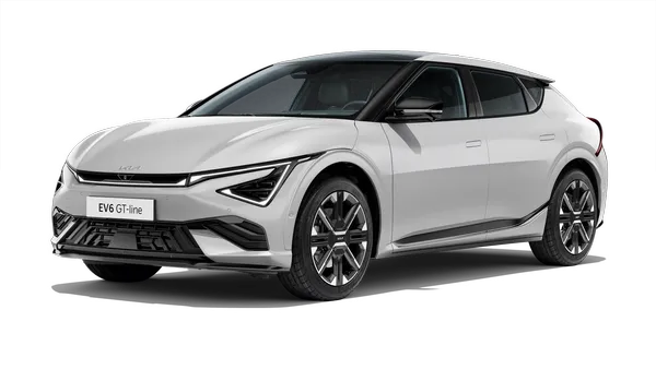
Kia EV6: Advanced Driver Assistance System (ADAS) / Advanced Driver Assistance System (Driving)
Contents:
Components and Components Location


1. Front View Camera
2. Front Radar
3. ADAS
driving ECU
|
4. Front Corner Radar
5. Rear Corner Radar
|
Driver Driving Assistance Switch Removal and Installation
|
•
|
When working on the high voltage system, the work should be performed by technicians who have
completed the relevant training. A lack of understanding of the high voltage system can lead to
serious accidents due to electric shock or short circuit.
|
|
•
|
When working on the high voltage system or related components, be sure to observe and be aware of
the "Safety Precautions, Cautions and Warnings". If not, it may cause serious accidents due
to electric shock or short circuit.
|
|
•
|
When working on high voltage system, make sure to check the Personal Protective Equipment (PPE) and
high voltage shut-off procedure.
|
|
| 1. |
Remove the steering wheel remote controller.
(Refer to Body - " Steering Wheel Remote Controller")
|
|
•
|
When working on the high voltage system, the work should be performed by technicians who have
completed the relevant training. A lack of understanding of the high voltage system can lead to
serious accidents due to electric shock or short circuit.
|
|
•
|
When working on the high voltage system or related components, be sure to observe and be aware of
the "Safety Precautions, Cautions and Warnings". If not, it may cause serious accidents due
to electric shock or short circuit.
|
|
•
|
When working on high voltage system, make sure to check the Personal Protective Equipment (PPE) and
high voltage shut-off procedure.
|
|
| 1. |
Install in the reverse order of removal.
|
ADAS Driving ECU (ADAS_DRV) Specification. ADAS Driving ECU (ADAS_DRV) On Vehicle Inspection
ADAS Driving ECU (ADAS_DRV) Specification
Item
|
Specification
|
Rated voltage (V)
|
12.0
|
Operation voltage (V)
|
9.0 - 16.0
|
Quantity
|
1
|
ADAS Driving ECU (ADAS_DRV) On Vehicle Inspection
Diagnostic with KDS
| 1. |
The ADAS driving ECU can be more quickly diagnosed for problems with the KDS. (Refer to "DTC
guide")
| (1)
|
Self diagnosis : Inspect the Diagnostic Trouble Code (DTC) with the KDS.
(Refer to DTC guide when fault code is found.)
|
| (2)
|
S/W Management : Controlling other features including system option setting and zero point
adjustment.
(S/W Management → Advanced Driver Assistance Systems_Driving → System Identification)
(S/W Management → Advanced Driver Assistance Systems_Driving → Variant Coding)
|
|
Refer to the KDS screen for operating conditions and details.
|
|
ADAS Driving ECU (ADAS_DRV) Removal and Installation
|
•
|
When working on the high voltage system, the work should be performed by technicians who have
completed the relevant training. A lack of understanding of the high voltage system can lead to
serious accidents due to electric shock or short circuit.
|
|
•
|
When working on the high voltage system or related components, be sure to observe and be aware of
the "Safety Precautions, Cautions and Warnings". If not, it may cause serious accidents due
to electric shock or short circuit.
|
|
•
|
When working on high voltage system, make sure to check the Personal Protective Equipment (PPE) and
high voltage shut-off procedure.
|
|
| 1. |
Remove the ADAS parking ECU bracket.
(Refer to Advanced Driver Assistance System (Parking) - "ADAS Parking
ECU (ADAS_PRK)")
|
| 2. |
Separate the ADAS driving ECU (ADAS_DRV) (A) after removing the nut.
Tightening torque :
9.0 - 11.0 N·m (0.92 - 1.12 kgf·m, 6.7 - 8.1 lb·ft)
|

|
| 3. |
Remove the ADAS_DRV (A) after disconnecting the connector (B).

|
|
•
|
When working on the high voltage system, the work should be performed by technicians who have
completed the relevant training. A lack of understanding of the high voltage system can lead to
serious accidents due to electric shock or short circuit.
|
|
•
|
When working on the high voltage system or related components, be sure to observe and be aware of
the "Safety Precautions, Cautions and Warnings". If not, it may cause serious accidents due
to electric shock or short circuit.
|
|
•
|
When working on high voltage system, make sure to check the Personal Protective Equipment (PPE) and
high voltage shut-off procedure.
|
|
| 1. |
Install in the reverse order of removal.
|
Front Radar Specification
Item
|
Specification
|
Rated voltage (V)
|
11.5 - 12.5
|
Operating voltage (V)
|
9.0 - 16.0
|
Mounting angle (°)
|
Horizontal
|
-0.8 to 0.8
|
Vertical
|
-0.4 to 0.4
|
Front Radar On Vehicle Inspection
Visual inspection
If the function of FCA, SCC, NSCC, or HDA 2 is not operable or DTC occurs, check the following below.
| 1. |
Checking bumper cleanliness : If the bumper is contaminated with snow or dust, may be disable during
operation.
|
| 2. |
Check the condition around the bumper : Warning lights may occur if metal stickers or foreign substances
are attached to the radar.
|
| 3. |
Checking bumper geometry or mounting status : Warning lights may occur if bumper or radar is not properly
installed after an accident.
|
Diagnostic with KDS
| 1. |
The front radar can be more quickly diagnosed for problems with the KDS. (Refer to "DTC guide")
| (1)
|
Self diagnosis : Inspect the Diagnostic Trouble Code (DTC) with the KDS.
(Refer to DTC guide when fault code is found.)
|
| (2)
|
S/W Management : Controlling other features including system option setting and zero point
adjustment.
(S/W Management → Front Radar → System Identification)
(S/W Management → Front Radar → Inspection/correction of the front - radar mounting angle)
(S/W Management → Front Radar → Inspection/correction of the front - radar mounting angle → C1
(Stop mode))
(S/W Management → Front Radar → Inspection/correction of the front - radar mounting angle → C2
(Driving mode))
|
|
Refer to the KDS screen for operating conditions and details.
|
|
| 2. |
Check the bumper, bracket, or radar when a diagnostic trouble code occurs.
|
•
|
Bumper : Installation status, bumper deformation.
|
|
•
|
Radar Bracket : Installation status, radar bracket deformation.
|
|
•
|
Radar : Faulty radar bolt or nut tightening, radar surface contamination.
|
|
Front Radar Removal
|
•
|
When working on the high voltage system, the work should be performed by technicians who have
completed the relevant training. A lack of understanding of the high voltage system can lead to
serious accidents due to electric shock or short circuit.
|
|
•
|
When working on the high voltage system or related components, be sure to observe and be aware of
the "Safety Precautions, Cautions and Warnings". If not, it may cause serious accidents due
to electric shock or short circuit.
|
|
•
|
When working on high voltage system, make sure to check the Personal Protective Equipment (PPE) and
high voltage shut-off procedure.
|
|
| 1. |
Perform the order below with the KDS before replacing the front radar.
(S/W Management → Front Radar → System Identification)
|
Refer to the KDS screen for operating conditions and details.
|
|
| 2. |
Remove the front bumper assembly.
(Refer to Body - "Front Bumper Assembly")
|
| 3. |
Remove the front radar.
Tightening torque :
9.0 - 11.0 N·m (0.92 - 1.12 kgf·m, 6.7 - 8.1 lb·ft)
|
| (1)
|
Disconnect the front radar connector (B).
|
| (2)
|
Remove the front radar (A) after removing the bolts.
|

|
Front Radar Installation
Tool Name / Number
|
Illustration
|
Description
|
Digital Inclinometer
09958 - 3T100
|

|
Used to calibrate the rear corner radar
Used to calibrate the front radar
|
|
•
|
When working on the high voltage system, the work should be performed by technicians who have
completed the relevant training. A lack of understanding of the high voltage system can lead to
serious accidents due to electric shock or short circuit.
|
|
•
|
When working on the high voltage system or related components, be sure to observe and be aware of
the "Safety Precautions, Cautions and Warnings". If not, it may cause serious accidents due
to electric shock or short circuit.
|
|
•
|
When working on high voltage system, make sure to check the Personal Protective Equipment (PPE) and
high voltage shut-off procedure.
|
|
|
Check the items below before performing the front radar
installation.
|
•
|
Align the tires in a straight direction.
|
|
•
|
Inspect the tire pressure.
|
|
•
|
Check the wheel alignment.
|
|
•
|
Check the suspension for damage.
|
|
•
|
Check that the radar surface is clean and deformed.
|
|
| 1. |
Before installing the front radar, check the last 2 digits of Lot, No (A).

|
| 2. |
Install the front radar.
Tightening torque :
9.0 - 11.0 N·m (0.92 - 1.12 kgf·m, 6.7 - 8.1 lb·ft)
|
| (1)
|
Install the front radar (A) after tightening the bolts.
|
| (2)
|
Connect the front radar connector (B).
|
|
| 3. |
Perform the order below with the KDS when replacing the front radar.
(S/W Management → Front Radar → Variant Coding)
|
| 4. |
Perform the order below with the KDS.
(S/W Management → Front Radar → Inspection/correction of the front - radar mounting angle)
|
| 5. |
Check the front radar vertical angle by using the digital inclinometer(A).
Horizontal Angle : 0° ± 0.8°
Vertical Angle : 0° ± 0.4°
|

|
•
|
Make sure to perform the zero setting horizontally before using a digital inclinometer.
|
|
•
|
Note that depending on the display method of the digital inclinometer, the ( + ) / ( - )
angle may be displayed differently.
|
|
|
| 6. |
Adjust to vertical installation angle by turning the adjusting screw (A) of the front radar.
|
–
|
turn clockwise : adjusting ( - ) angle
|
|
–
|
turn counterclockwise : adjusting ( + ) angle
|

|
| 7. |
Install the front bumper assembly.
(Refer to Body - "Front Bumper Assembly")
|
Check that the front radar is clean before installing the front bumper assembly.
|
|
| 8. |
Perform the front radar inspection/calibration procedure.
(Refer to Front Radar - "Adjustment")
|
Front Radar Adjustment
Tool Name / Number
|
Illustration
|
Description
|
SCC Setting Beam
09964 - C1200
|

|
Used to calibrate the front radar
Used to calibrate the front view camera
|
Vertical Plumb
09958 - 3T010
|

|
Used to calibrate the front radar
|
Front Radar Setting Reflector
09964 - C1100
|

|
Used to calibrate the front radar
|
Calibration Reflector
0K964 - J5100
|

|
Used to calibrate the front radar
|
Front Radar Setting Tripod
09964 - C1300
|

|
Used to calibrate the front radar
|
Front Radar Installation Angle Inspection / Adjustment Overview
|
•
|
The forward radar detects objects in front of the vehicle and measures their speed to recognize the
distance between the vehicle and the objects.
|
|
•
|
If the forward radar angle is not properly calibrated and adjusted, some functions may malfunction.
|
|
The front radar installation angle inspection / adjustment are needed in
the following cases.
|
•
|
When the front radar is reinstalled.
|
|
•
|
When the front radar is replaced.
|
|
•
|
When DTC occurs for the calibration.
|
|
•
|
In the case of damage to the front radar or its periphery.
|
|
•
|
If there is a problem with the front radar detection and recognition function.
|
|
|
•
|
When driving for aobve 10 minutes at 65 km/h after performing the stop mode, correction accuracy is
improved.
(Drive on straight road which has metallic reflector.)
|
|
•
|
When the front radar correction is not available in stop mode, perform the correction in driving
mode.
|
|
Front Radar Mounting Angle Inspection / Correction - Stop Mode
|
Check the following below before performing the front radar mounting angle
inspection / calibration.
|
•
|
Park the vehicle on flat ground.
|
|
•
|
Align the tires in a straight direction.
|
|
•
|
Inspect the tire pressure.
|
|
•
|
Check the wheel alignment.
|
|
•
|
Check the suspension for damage.
|
|
•
|
Check the front bumper or front radar cover bracket is deformed and damaged.
|
|
|
•
|
Perform front radar calibration with the exclusive SST and KDS.
|
|
•
|
Remove objects (metal plates, resins, etc.) that may cause electric signal interference from the
area where front radar alignment is performed.
|
|
•
|
Install the reflector in the correct position. (A calibration of the front radar may fail if the
reflector is not installed in the designated area.)
|
|
•
|
Be sure not to move the vehicle when performing the front radar calibration.
|
|
•
|
Perform the front radar calibration during the POWER ON state.
|
|
•
|
Perform the inspection/calibration of the front radar mounting angle in the clearance of 8 m (26.2
ft.) in front of the front bumper, 4 m (13.2 ft.)in width, and 2 m (6.6 ft.) in height.
|
|
| 1. |
Park the vehicle in a flat ground.

|
| 2. |
Mark the center point (A) after measuring the distance on top of the windshield glass.

|
| 3. |
Mark the center point of emblem (B).

|
| 4. |
Mount the SCC setting beam (09964 - C1200) on the front radar setting tripod (09964 - C1300).

|
| 5. |
Place the SCC setting beam (09964 - C1200) more than 2.6 m (8.53 ft) away from the front of the vehicle.

|
| 6. |
Match the vertical laser line to points (A) and (B) using the SCC setting beam (09964 - C1200).

|
| 7. |
Mark the point (C) at a distance 2.4 - 2.6 m (7.87 - 8.53 ft) away from (B) point.

|
| 8. |
Mark the location (D) as shown below at 6 mm (0.23 in) away from (C) to the left (passenger's side) of
the vehicle.

|
| 9. |
Remove the SCC setting beam (09964 - C1200) from the front radar setting tripod (09964 - C1300).
|
| 10. |
Mount the front radar setting reflector (09964 - C1100) to the front radar setting tripod (09964 - C1300).

|
| 11. |
Mount the calibration reflector (0K964 - J5100) to the front radar setting reflector (09964 - C1100).

|
| 12. |
Set the reflector horizontal using the leveler (A) which is built in the front radar setting tripod (09964
- C1300).

|
| 13. |
Align the plumb (A) of the front radar setting reflector (09964 - C1100) with point (D).

|
| 14. |
Set the height of the calibration reflector (0K964 - J5100) to 332 mm (13.07 in.).

|
| 15. |
Remove the plumb bob from the front radar setting reflector (09964 - C1100).
|
The adjustment of the front radar may be failed if the plumb is not removed.
|
|
| 16. |
Make sure that there is no debris, or reflecting object on the surface of the radar.
|
| 17. |
Perform the order below with the KDS.
(S/W Management → Front Radar → Inspection/correction of the front - radar mounting angle → C1 (Stop mode))
|
Refer to the KDS screen for operating conditions and details.
|
|
| 18. |
In case of failure of the front radar angle inspection or correction, check the front radar and inspection
and correction condition.
|
Front Radar Mounting Angle Inspection / Correction - Driving Mode
|
Check the following below before performing the front radar mounting angle
inspection / calibration.
|
•
|
Inspect the tire pressure.
|
|
•
|
Check the wheel alignment.
|
|
•
|
Check the suspension for damage.
|
|
•
|
Check the front bumper or front radar cover bracket is deformed and damaged.
|
|
|
The driving mode (C2) operates the correction through actual road driving.
(Conducted on roads with metallic fixed reflectors such as guardrails.)
|
| 1. |
Perform the order below with the KDS.
(S/W Management → Front Radar → Inspection/correction of the front - radar mounting angle → C2 (Driving
mode))
|
Refer to the KDS screen for operating conditions and details.
|
|
| 2. |
In case of front radar inspection / correction failure, check the inspection / correction conditions.
|
Front Camera On Vehicle Inspection
Visual inspection
If the function of FCA, LKA, BCA, ISLA, DAW, HBA, LFA, HDA or HDA2 is not operable or DTC occurs, check the
following below.
| 1. |
Check if the windshield is clean.
|
–
|
Snow, dust, or stickers around the camera lens may result in poor performance.
|
|
–
|
Damaged or cracked glass around the camera lens may result in poor performance.
|
|
–
|
Any tinting or coatings around the camera lens may result in poor performance.
|
|
| 2. |
Check the condition of the crash pad.
|
–
|
Any objects on the crash pad under the camera may result in poor performance.
|
|
| 3. |
Check the cover, coupler or front camera when a diagnostic trouble code occurs.
|
–
|
Cover : Installation status and foreign substance entrance.
|
|
–
|
Coupler : Installation status, foreign substance entrance and coupler deformation.
|
|
–
|
Front camera unit : Damages and contamination on the front camera lens.
|
|
| 4. |
Check the switch operation status.
|
–
|
Press the lane driving assistant button (A) and see if the indicator light (B) illuminates.(Check
the LKA system if the indicator light does not illuminates.)

|
|
–
|
Press the lane driving assistant button (A) and see if the indicator light (B) illuminates. (Check
the LFA system if the indicator light does not illuminates.)

|
|
Diagnostic with KDS
| 1. |
The front view camera can be more quickly diagnosed for problems with the KDS. (Refer to "DTC
guide")
| (1)
|
Self diagnosis : Inspect the Diagnostic Trouble Code (DTC) with the KDS.
(Refer to DTC guide when fault code is found.)
|
| (2)
|
S/W Management : Controlling other features including system option setting and zero point
adjustment.
(S/W Management → Front View Camera → System Identification)
(S/W Management → Front View Camera → Variant Coding)
(S/W Management → Front View Camera → SPTAC Calibration)
|
|
Refer to the KDS screen for operating conditions and details.
|
|
Front Camera Removal and Installation
|
•
|
When working on the high voltage system, the work should be performed by technicians who have
completed the relevant training. A lack of understanding of the high voltage system can lead to
serious accidents due to electric shock or short circuit.
|
|
•
|
When working on the high voltage system or related components, be sure to observe and be aware of
the "Safety Precautions, Cautions and Warnings". If not, it may cause serious accidents due
to electric shock or short circuit.
|
|
•
|
When working on high voltage system, make sure to check the Personal Protective Equipment (PPE) and
high voltage shut-off procedure.
|
|
| 1. |
Perform the order below with the KDS before removing the front camera.
(S/W Management → Front View Camera → System Identification)
|
Refer to the KDS screen for operating conditions and details.
|
|
| 2. |
Turn the POWER OFF, separate the auxiliary battery (12 V) ( - ) terminal, and disconnect the high voltage
service interlock connector.
| (1)
|
Open the front trunk (A).

|
| (2)
|
Open the auxiliary 12 V battery service cover (A).

|
| (3)
|
Turn the POWER OFF, separate the auxiliary battery (12 V) ( - ) terminal (A).
Tightening torque :
7.8 - 9.8 N·m (0.8 - 1.0 kgf·m, 5.8 - 7.2 lb·ft)
|

|
| (4)
|
Disconnect the service interlock connector (A).

|
•
|
Wait more than 5 minutes for capacitor of the high voltage battery system to be
discharged completely.
|
|
•
|
When working on a vehicle during discharging the capacitor, it can cause an
electrical shock or injury, so follow the manual.
|
|
|
The service interlock connector cannot be completely removed.

|
|
|
| 3. |
Remove the multi sensor cover.
(Refer to Body - "Multi Sensor Corver")
|
| 4. |
Disconnect the front camera connector (A).

|
| 5. |
Remove the front camera (A) by pulling both hooks (B) in the direction of the arrow.

|
Clip position :

|
|
|
•
|
When working on the high voltage system, the work should be performed by technicians who have
completed the relevant training. A lack of understanding of the high voltage system can lead to
serious accidents due to electric shock or short circuit.
|
|
•
|
When working on the high voltage system or related components, be sure to observe and be aware of
the "Safety Precautions, Cautions and Warnings". If not, it may cause serious accidents due
to electric shock or short circuit.
|
|
•
|
When working on high voltage system, make sure to check the Personal Protective Equipment (PPE) and
high voltage shut-off procedure.
|
|
| 1. |
Install in the reverse order of removal.
|
Check that the front camera mounting area (windshield glass) is clean before installing the front
camera.
|
|
| 2. |
Perform the order below with the KDS when replacing the front view camera.
(S/W Management → Front View Camera → Variant Coding)
|
Refer to the KDS screen for operating conditions and details.
|
|
| 3. |
Enter the specification value read from the existing camera into the new front view camera.
|
| 4. |
Perform the front camera calibration.
(Refer to Front Camera - "Adjustment")
|
| 5. |
Perform Over The Air (OTA) controller S/W update with KDS.
(Refer to Body - "Over The Air (OTA)")
|
Front Camera Adjustment
Tool Name / Number
|
Illustration
|
Description
|
Front View Camera Calibration target
09890 - 3V100
|

|
Used to calibrate the front camera
|
SCC Setting Beam
09964 - C1200
|
|
Used to calibrate the front radar
Used to calibrate the front camera
|
|
Perform the front camera calibration in the following cases.
|
•
|
When the front camera is reinstalled.
|
|
•
|
When the front camera is replaced.
|
|
•
|
When the front camera bracket is deformed.
|
|
•
|
When the windshield glass is replaced.
|
|
•
|
When the DTC occurs for the front camera.
|
Check the items below before performing the camera calibration.
|
•
|
Align the tires in a straight direction.
|
|
•
|
Inspect the tire pressure.
|
|
•
|
Check the wheel alignment.
|
|
•
|
Check the suspension for damage.
|
|
•
|
Check that the windshield glass is clean.
|
|
| Service Point Target Auto Calibration (SPTAC) |
| 1. |
Mark the center point (A) after measuring the distance on top of the windshield glass.
|
| 2. |
Mark the center point (A) of the emblem.
|
| 3. |
Mount the SCC setting beam (09964 - C1200) on the front radar setting tripod (09964 - C1300).
|
| 4. |
Place the SCC setting beam (09964 - C1200) more than 2.6 m (8.53 ft) away from the front of the vehicle.
|
| 5. |
Match the vertical laser line to points (A) and (B) using the SCC setting beam (09964 - C1200).
|
| 6. |
Mark the center point (C) of the hood using the laser vertical line.

|
| 7. |
Remove the SCC setting beam (09964 - C1200) from the front radar setting tripod (09964 - C1300).
|
| 8. |
Install the SCC setting beam (09964 - C1200) in the center of the roof.

|
| 9. |
Allow the laser of the SCC setting beam (09964 - C1200) to pass through the center point (C).

|
The SCC Setting Beam (09964 - C1200) must be set to 'ON' and the holding (locking)
function is not used.


|
|
| 10. |
The height of the front camera calibration target (09890 - 3V100) is adjusted to be 90 ± 2 cm (36 ± 0.8
in.) from the ground.
|
| 11. |
Place the front camera calibration target (09890 - 3V100) so that it maintains a distance of 0 cm (0 in.)
from the bumper. [Maximum tolerance : 10 cm (4 in.)]

|
| 12. |
Install the front view camera calibration target (09890 - 3V100) center (A) in line with the laser vertical
line of the SCC setting beam (09964 - C1200). [Maximum tolerance : 5cm (2 in.)]

|
•
|
Align the front view camera calibration target (09890 - 3V100) referring to the tolerance
angle below.
|
|
•
|
The vehicle horizontal plane shall be completely parallel to the target horizontal plane (±
1°).
|
|
–
|
The left and right tilt tolerance (±1°) is very important and is sensitively affected by
the flatness of the floor.
|


|
|
| 13. |
Perform the order below with the KDS.
(S/W Management → Front View Camera → SPTAC Calibration)
|
Refer to the KDS screen for operating conditions and details.
|
|
| 14. |
Place the front view camera calibration target (09890 - 3V100) so that it maintains a distance of 120 cm
(48 in.) from the bumper. (Maximum tolerance : 20 cm (8 in.))

|
| 15. |
Install the front view camera calibration target (09890 - 3V100) center (A) in line with the laser vertical
line of the SCC setting beam (09964 - C1200). [Maximum tolerance : 5cm (2 in.)]
|
•
|
Align the front view camera calibration target (09890 - 3V100) referring to the tolerance
angle below.
|
|
•
|
The vehicle horizontal plane shall be completely parallel to the target horizontal plane (±
1°).
|
|
–
|
The left and right tilt tolerance (±1°) is very important and is sensitively affected by
the flatness of the floor.
|
|
|
| 16. |
Perform the order below with the KDS.
(S/W Management → Front View Camera → SPTAC Calibration)
|
Refer to the KDS screen for operating conditions and details.
|
|
| 17. |
Check the DTC and warning lamp after erasing the DTC using the KDS.
|
Front Corner Radar Specification
Item
|
Specification
|
Rated voltage (V)
|
12.0
|
Operation voltage (V)
|
9.0 - 16.0
|
Quantity
|
2
|
Front Corner Radar On Vehicle Inspection
Visual inspection
If the function of FCA, SCC, NSCC, or HDA 2 is not operable or DTC occurs, check the following below.
| 1. |
Checking bumper cleanliness : If the bumper is contaminated with snow or dust, may be disable during
operation.
|
| 2. |
Check the condition around the bumper : Warning lights may occur if metal stickers or foreign substances
are attached to the radar.
|
| 3. |
Checking bumper geometry or mounting status : Warning lights may occur if bumper or radar is not properly
installed after an accident.
|
Diagnostic with KDS
| 1. |
The front corner radar can be more quickly diagnosed for problems with the KDS. (Refer to "DTC
guide")
| (1)
|
Self diagnosis : Inspect the Diagnostic Trouble Code (DTC) with the KDS.
(Refer to DTC guide when fault code is found.)
|
| (2)
|
S/W Management : Controlling other features including system option setting and zero point
adjustment.
(S/W Management → Front Corner/Rear Corner Radar → System Identification)
(S/W Management → Corner Radar → Variant Coding)
(S/W Management → Corner Radar → Front Corner / Rear Corner Radar Calibration)
|
|
Refer to the KDS screen for operating conditions and details.
|
|
| 2. |
Check the bumper, bracket, or radar when a diagnostic trouble code occurs.
|
•
|
Bumper : Installation status, bumper deformation.
|
|
•
|
Radar Bracket : Installation status, radar bracket deformation.
|
|
•
|
Radar : Faulty radar bolt or nut tightening, radar surface contamination.
|
|
Front Corner Radar Removal
|
•
|
When working on the high voltage system, the work should be performed by technicians who have
completed the relevant training. A lack of understanding of the high voltage system can lead to
serious accidents due to electric shock or short circuit.
|
|
•
|
When working on the high voltage system or related components, be sure to observe and be aware of
the "Safety Precautions, Cautions and Warnings". If not, it may cause serious accidents due
to electric shock or short circuit.
|
|
•
|
When working on high voltage system, make sure to check the Personal Protective Equipment (PPE) and
high voltage shut-off procedure.
|
|
| 1. |
Perform the order below with the KDS before replacing the front corner radar.
(S/W Management → Front Corner/Rear Corner Radar → System Identification)
|
Refer to the KDS screen for operating conditions and details.
|
|
| 2. |
Remove the front bumper assembly.
(Refer to Body - "Front Bumper Assembly")
|
| 3. |
Disconnect the front corner radar connector (A).

|
| 4. |
Remove the front corner radar (A) after removing the screws.
Tightening torque :
3.5 - 5.7 N·m (0.36 - 0.58 kgf·m, 2.6 - 4.2 lb·ft, 31.2 - 50.3 lb·in)
|

|
| 5. |
Remove the front radar (A) by pressing the fixing hook (B).

|
If the bracket is deformed or damaged, the front corner radar will not operate normally.
|
|
Clip position :
|
|
Front Corner Radar Installation
|
•
|
When working on the high voltage system, the work should be performed by technicians who have
completed the relevant training. A lack of understanding of the high voltage system can lead to
serious accidents due to electric shock or short circuit.
|
|
•
|
When working on the high voltage system or related components, be sure to observe and be aware of
the "Safety Precautions, Cautions and Warnings". If not, it may cause serious accidents due
to electric shock or short circuit.
|
|
•
|
When working on high voltage system, make sure to check the Personal Protective Equipment (PPE) and
high voltage shut-off procedure.
|
|
| 1. |
Install in the reverse order of removal.
|

1) Parts number
2) FL, FR, RL, RR
|
|
| 2. |
Perform the order below with the KDS when replacing the front corner radar.
(S/W Management → Corner Radar → Variant Coding)
|
Refer to the KDS screen for operating conditions and details.
|
|
| 3. |
Perform the order below with the KDS.
(S/W Management → Corner Radar → Front Corner/ Rear Corner Radar Calibration)
|
Check the items below before performing the front corner radar
calibration.
|
•
|
Inspect the tire pressure.
|
|
•
|
Check the wheel alignment.
|
|
•
|
Check the suspension for damage.
|
|
•
|
Check the front bumper assembly for damage and deformation.
|
|
|
Refer to the KDS screen for operating conditions and details.
|
|
Rear Corner Radar Specification
Item
|
Specification
|
Rated voltage (V)
|
12.0
|
Operation voltage (V)
|
9.0 - 16.0
|
Quantity
|
2
|
Rear Corner Radar On Vehicle Inspection
Visual inspection
If the function of FCA, BCW/BCA, SEW/SEA, NSCC, RCCW/RCCA or HDA2 is not operable or DTC occurs, check the
following below.
| 1. |
Checking bumper cleanliness: If the bumper is contaminated with snow or dust, performance will be reduced.
|
| 2. |
Check the condition around the bumper : Warning lights may occur if metal stickers or foreign substances
are attached to the radar.
|
| 3. |
Checking bumper geometry or mounting status : Warning lights may occur if bumper or radar is not properly
installed after an accident.
|
| 4. |
Check the operation status of the switch: Press the switch to check whether the LED works.
|
Diagnostic with KDS
| 1. |
The rear corner radar can be more quickly diagnosed for problems with the KDS. (Refer to "DTC
guide")
| (1)
|
Self diagnosis : Inspect the Diagnostic Trouble Code (DTC) with the KDS.
(Refer to DTC guide when fault code is found.)
|
| (2)
|
S/W Management : Controlling other features including system option setting and zero point
adjustment.
(S/W Management → Front Corner/Rear Corner Radar → System Identification)
(S/W Management → Corner Radar → Variant Coding)
(S/W Management → Corner Radar → Front Corner/ Rear Corner Radar Calibration)
|
|
Refer to the KDS screen for operating conditions and details.
|
|
| 2. |
Check the bumper, bracket, or radar when a diagnostic trouble code occurs.
|
•
|
Bumper : Installation status, bumper deformation.
|
|
•
|
Radar Bracket : Installation status, radar bracket deformation.
|
|
•
|
Radar : Faulty radar bolt or nut tightening, radar surface contamination.
|
|
Rear Corner Radar Removal
|
•
|
When working on the high voltage system, the work should be performed by technicians who have
completed the relevant training. A lack of understanding of the high voltage system can lead to
serious accidents due to electric shock or short circuit.
|
|
•
|
When working on the high voltage system or related components, be sure to observe and be aware of
the "Safety Precautions, Cautions and Warnings". If not, it may cause serious accidents due
to electric shock or short circuit.
|
|
•
|
When working on high voltage system, make sure to check the Personal Protective Equipment (PPE) and
high voltage shut-off procedure.
|
|
Rear Corner Radar [Standard]
| 1. |
Perform the order below with the KDS before replacing the rear corner radar.
(S/W Management → Front Corner/Rear Corner Radar → System Identification)
|
Refer to the KDS screen for operating conditions and details.
|
|
| 2. |
Remove the rear bumper assembly.
(Refer to Body - "Rear Bumper Assembly")
|
| 3. |
Disconnect the rear corner radar connector (A).

|
| 4. |
Remove the rear corner radar (A) after removing the screws.

|
| 5. |
Remove the rear corner radar (A) after pressing the fixing hooks.

|
the bracket is deformed or damaged, the rear corner radar will not operate normally.
|
|
Clip position :
|
|
Rear Corner Radar [Option]
| 1. |
Perform the order below with the KDS before replacing the rear corner radar.
(S/W Management → Front Corner/Rear Corner Radar → System Identification)
|
Refer to the KDS screen for operating conditions and details.
|
|
| 2. |
Remove the rear bumper under cover.
(Refer to Body - "Rear Bumper Assembly")
|
| 3. |
Disconnect the rear corner radar connector (A).

|
| 4. |
Remove the rear corner radar (A) after removing the screws.

|
| 5. |
Remove the rear corner radar (A) after pressing the fixing hooks.

|
the bracket is deformed or damaged, the rear corner radar will not operate normally.
|
|
Clip position :
|
|
BCW & RCCW indicator
| 1. |
Remove the mirror.
(Refer to Body - "Outside Mirror")
|
Rear Corner Radar Installation
|
•
|
When working on the high voltage system, the work should be performed by technicians who have
completed the relevant training. A lack of understanding of the high voltage system can lead to
serious accidents due to electric shock or short circuit.
|
|
•
|
When working on the high voltage system or related components, be sure to observe and be aware of
the "Safety Precautions, Cautions and Warnings". If not, it may cause serious accidents due
to electric shock or short circuit.
|
|
•
|
When working on high voltage system, make sure to check the Personal Protective Equipment (PPE) and
high voltage shut-off procedure.
|
|
Rear Corner Radar
| 1. |
Install in the reverse order of removal.
|
1) Parts number
2) FL, FR, RL, RR
|
|
| 2. |
Perform the order below with the KDS when replacing the rear corner radar.
(S/W Management → Corner Radar → Variant Coding)
|
Refer to the KDS screen for operating conditions and details.
|
|
| 3. |
Perform the order below with the KDS.
(S/W Management → Corner Radar → Front Corner/ Rear Corner Radar Calibration)
|
Check the items below before performing the rear corner radar
calibration.
|
•
|
Inspect the tire pressure.
|
|
•
|
Check the wheel alignment.
|
|
•
|
Check the suspension for damage.
|
|
•
|
Check the rear bumper is deformed and damaged.
|
|
|
Refer to the KDS screen for operating conditions and details.
|
|
BCW & RCCW indicator
| 1. |
Install in the reverse order of removal.
|
In Cabin Cam Description and Operation
| Description and Operation |
DDMS: Direct Driver Monitoring System
1st Warning
|
2nd Warning
|
3rd Deceleration Control
|
4th Stop Control
|
DDMS warning pop-up occurs
1 beep
|
DDMS warning pop-up occurs
ICC warning light flashing
Continuous beep
Steering vibration (haptic)
|
ICC warning light flashing
|
-
|
In Cabin Cam Removal and Installation
|
•
|
When working on the high voltage system, the work should be performed by technicians who have
completed the relevant training. A lack of understanding of the high voltage system can lead to
serious accidents due to electric shock or short circuit.
|
|
•
|
When working on the high voltage system or related components, be sure to observe and be aware of
the "Safety Precautions, Cautions and Warnings". If not, it may cause serious accidents due
to electric shock or short circuit.
|
|
•
|
When working on the high voltage system, make sure to check the Personal Protective Equipment (PPE)
and high voltage shut-off procedure.
|
|
In Cabin Cam (ICC) Driver Camera
| 1. |
Perform in the order below with the KDS before replacing the ICC driver camera.
(S/W Management → In-Cabin Camera → System Identification)
|
Refer to the KDS screen for operating conditions and details.
|
|
| 2. |
Disconnect the auxiliary battery (12 V) negative ( - ) terminal and high voltage service interlock
connector after turning the POWER OFF.
|
| 3. |
Remove the steering column shroud upper cover.
(Refer to Body -"Steering Column Shroud Panel")
|
| 4. |
Remove the in cabin cam driver camera (A).

|
In Cabin Cam (ICC) Unit
| 1. |
Perform in the order below with the KDS before replacing the ICC Unit.
(S/W Management → In-Cabin Camera → System Identification)
|
Refer to the KDS screen for operating conditions and details.
|
|
| 2. |
Remove the crash pad lower panel.
(Refer to Body - "Crash Pad Panel")
|
| 3. |
Separate the in cabin cam (A) after disconnecting the connetors (B).

|
| 4. |
Remove the in cabin cam unit (A) after removing the nuts.
Tightening torque :
7.8 - 11.8 N·m (0.8 - 1.2 kgf·m, 5.8 - 8.7 lb·ft)
|

|
|
•
|
When working on the high voltage system, the work should be performed by technicians who have
completed the relevant training. A lack of understanding of the high voltage system can lead to
serious accidents due to electric shock or short circuit.
|
|
•
|
When working on the high voltage system or related components, be sure to observe and be aware of
the "Safety Precautions, Cautions and Warnings". If not, it may cause serious accidents due
to electric shock or short circuit.
|
|
•
|
When working on the high voltage system, make sure to check the Personal Protective Equipment (PPE)
and high voltage shut-off procedure.
|
|
| 1. |
Install in the reverse order of removal.
|
| 2. |
Perform Over The Air (OTA) controller S/W update with KDS.
(Refer to Body - "Over The Air (OTA)")
|
Other information:
Kia EV6 (CV/CV1A) 2022-2026 Workshop Manual: Head-Up Display (HUD) : (if equipped)
The Kia EV6 Head-Up Display (HUD) is an advanced transparent projection system that displays important driving
information directly onto the windshield within the driver’s field of vision.
This technology allows the Kia EV6 driver to monitor critical driving information without taking attention away
from
the road ahead.
The HUD system can display information from the instrument cluster, navigation system, and various driver
assistance
technologies in real time.
Kia EV6 (CV/CV1A) 2022-2026 Workshop Manual: Evasive Steering Assist function: (if equipped)
The Kia EV6 Evasive Steering Assist function is part of the Forward Collision-Avoidance Assist system and is
designed
to help reduce the risk of collisions through intelligent steering intervention.
The Evasive Steering Assist function in the Kia EV6 provides the following emergency assistance feature:
Emergency Steering
Emergency Steering (Driver steering assist)
A: Emergency Steering
The Kia EV6 Emergency Steering Driver Assist function can alert the driver using multiple warning methods when a
possible collision risk is detected.