
Kia EV6: Heating,Ventilation And Air Conditioning / Heater
Contents:
- Components and Components Location. Auto Defogging Actuator Description and Operation
- Auto Defogging Actuator Removal and Installation
- Auto Defogging Actuator Inspection
- Evaporator Core Removal and Installation
- Heater Unit Removal and Installation
- Mode Control Actuator Description and Operation
- Mode Control Actuator Removal and Installation
- Mode Control Actuator Inspection
- PTC Heater Description and Operation
- PTC Heater Removal and Installation
- PTC Heater Inspection
- Temperature Control Actuator Description and Operation
- Temperature Control Actuator Removal and Installation
- Temperature Control Actuator Inspection
Components and Components Location. Auto Defogging Actuator Description and Operation
Components and Components Location
| Component |

| 1. Driver's Side Seat Shower Duct 2. Driver's Side Mode Control Actuator 3. Driver's Side Temperature Control Actuator 4. Rear Heating Temperature Control actuator 5. Rear Cooling Temperature Control actuator 6. Passenger's Side Shower Duct 7. Passenger's Side Mode Condrol Actuator 8. Passenger's Side Temperature Control Actuator |
9. Auto Defogging Actuator 10. Inner Condenser 11. PTC Heater 12. Heater Unit Lower Cover 13. Evaporator Core 14. Evaporator Temperature Sensor 15. Heater Module 16. Air Purification Unit |
Auto Defogging Actuator Description and Operation
| Description |
That detects fogging with a auto defogging sensor and automatically operates the air conditioning system to prevent
fogging.
Auto Defogging Actuator Removal and Installation
| Removal |
|

| 1. |
Remove the glove box housing.
(Refer to Body - "Glove Box")
|
| 2. |
Remove the auto defogging actuator.
|

| Installation |
|
| 1. |
Install in the reverse order of removal.
|
Auto Defogging Actuator Inspection
| Inspection |
| 1. |
Turn POWER OFF.
|
| 2. |
Disconnect the auto defogging actuator connector.
(Refer to Heater - "Auto Defogging Actuator")
|
| 3. |
Connect the power ( + ) terminal to the 3 terminal of the auto defogging actuator connector and the (-)
terminal to the 4 terminal and check whether the motor is running. When connected in the opposite direction,
check if it operates in reverse.
|

| 4. |
Connect the auto defogging actuator connector.
|
| 5. |
Turn POWER ON.
|
| 6. |
Measure the terminal voltage between 5 and 6.
* Feedback the current position of the actuator to the control.
|
| 7. |
If the measured voltage does not match the specifications, replace it with a new auto defogging actuator.
|
Evaporator Core Removal and Installation
| Removal |
| 1. |
Remove the heater unit.
(Refer to Heater - "Heater Unit")
|
| 2. |
Remove the inner condenser cover.
|

| 3. |
Remove the heater unit lower cover (A) after removing the screws.
|


| 4. |
Remove the evaporator core (A) in the direction of the arrow.
|


| Installation |
| 1. |
Install in the reverse order of removal.
|
Heater Unit Removal and Installation
| Removal |
|
| 1. |
Perform the high voltage shut off procedure.
(Refer to General Information - "High Voltage Shut-off
Procedures")
|
| 2. |
Recover the refrigerant with Recovery/Recycling/Charging equipment.
(Refer to Air conditioning System - "Refrigerant
Recovery/Recycling/Charging/Vacuum/Leak Test")
|
| 3. |
Remove the cowl cross bar assembly.
(Refer to Body - "Cowl Cross Bar Assembly")
|
| 4. |
Disconnect the expansion valve connector (A).
|

| 5. |
Remove the suction & liquid tube assembly (A) after removing the bolts.
[Inner Conderser Side]
[Evaporator Side]
|


| 6. |
Separate the high voltage cable (A) after disconnecting the PTC heater high voltage cable connector (B).
|

| 7. |
Disconnect the rear heating duct connector (A).
[Driver Side]
[Passenger Side]
|


| 8. |
Remove the rear heating duct (A) after removing the nut.
[Driver Side]
[Passenger Side]
|


| 9. |
Remove the heater unit (A) after removing the bolt.
|

| Installation |
|
| 1. |
Install in the reverse order of removal.
|
Mode Control Actuator Description and Operation
| Description |
| • |
It is operated by the auto temperature control unit and controls the position of the mode control door to
adjust the wind direction mode.
|
| • |
It consists of an actuator motor that moves the mode door and a potentiometer that detects the position of
the mode door. the wind direction mode in the order of Vent → Bi-Level → Floor → Mix
|
Mode Control Actuator Removal and Installation
| Removal |
|
Driver's Side Mode Control Actuator
| 1. |
Remove the crash pad assembly.
(Refer to Body - "Crash Pad Assembly")
|
| 2. |
Remove the actuator (A) after removing the screws.
|

Passenger's Side Mode Control Actuator
| 1. |
Remove the steering column module (SCM).
(Refer to Steering System - "Steering Column Module
(SCM)")
|
| 2. |
Remove the actuator.
|

| Installation |
|
| 1. |
Install in the reverse order of removal.
|
Mode Control Actuator Inspection
| Inspection |
| 1. |
Turn POWER OFF.
|
| 2. |
Disconnect the mode control actuator connector.
(Refer to Heater - "Mode Control Actuator")
|
| 3. |
Connect the power ( + ) terminal to the terminal 3 of the mode control actuator connector and the ( - )
terminal to the terminal 4 and check whether the motor operates. When connecting in the opposite direction,
check if it operates in reverse.
[Driver's Side]
[Passenger's Side]
|
| 4. |
Connect the mode control actuator connector.
|
| 5. |
Turn POWER ON.
|
| 6. |
Measure the terminal voltage.
[Driver's seat] : between 7 - 6.
[Passenger's seat] : between 5 - 6.
* Feedback the current position of the actuator to the control.
|
| 7. |
If the measured voltage does not match with the specifications, replace it with a new mode control
actuator.
|
PTC Heater Description and Operation
| Description |
| • |
The PTC (Positive Temperature Coefficient) heater is a device that is mounted on the rear side of the
heater core and directly heats the air passing through the heater core to heat the room.
|
| • |
The PTC heater is an electric heating device using a PTC element as an auxiliary heating device to
supplement the insufficient indoor heating heat source.
|
PTC Heater Removal and Installation
| Removal |
|
| 1. |
Perform the high voltage shut off procedure.
(Refer to General Information - "High Voltage Shut-off
Procedures")
|
| 2. |
Remove the crash pad center panel.
(Refer to Body - "Crash Pad Panel")
|
| 3. |
Remove the front console cover.
(Refer to Body - "Front Console Cover")
|
| 4. |
Disconnect the passenger's side duct sensor connector (A).
|

| 5. |
Remove the passenger's side shower duct (A) after removing the screw.
|

| 6. |
Separate the high voltage cable (A) after disconnecting the PTC heater high voltage cable connector (B).
|
| 7. |
Remove the clips (A).
|


| 8. |
Separate PTC heater signal wiring (B) after disconnecting the connector (A).
|

| 9. |
Disconnect the PTC heater ground wire (A) after removing the bolt.
|

| 10. |
Remove the PTC heater (A) after removing the screws.
|


| Installation |
|
| 1. |
Install in the reverse order of removal.
|
PTC Heater Inspection
| Inspection |
| 1. |
Check if there is an output signal (actuation request) from the A/C controller.
|
| 2. |
Inspect the interlock with a KDS to see if there is a problem.
|
| 3. |
Check that low voltage (12.0 V) is supplied.
|
| 4. |
For inspection, refer to the pin information below.
[Main Power Connector]
[Signal Connector]
|


Temperature Control Actuator Description and Operation
| Description |
It is operated by the auto temperature control unit and controls the position of the temperature control door to
adjust the temperature of the discharge air.
Temperature Control Actuator Removal and Installation
| Removal |
|
Driver's Side Temperature Control Actuator
| 1. |
Remove the crash pad lower panel.
(Refer to Body - "Crash Pad Panel")
|
| 2. |
Disconnect the driver's side duct sensor connector (A).
|

| 3. |
Remove the driver's side shower duct (A) after removing the screw.
|

| 4. |
Remove the actuator.
|

Passenger's Side Temperature Control Actuator
| 1. |
Remove the glove box housing.
(Refer to Body - "Glove Box")
|
| 2. |
Remove the actuator.
|

Rear Temperature Control Actuator
| 1. |
Remove the cowl cross bar assembly.
(Refer to Body - "Cowl Cross Bar Assembly")
|
| 2. |
Remove the rear cooling actuator (A) and the rear heating actuator (B) after removing the screws.
|

| Installation |
|
| 1. |
Install in the reverse order of removal.
|
Temperature Control Actuator Inspection
| Inspection |
| 1. |
Turn POWER OFF.
|
| 2. |
Disconnect the temperature control actuator connector.
(Refer to Heater - "Temperature Control Actuator")
|
| 3. |
Connect the power ( + ) terminal to the 3 terminal of the actuator connector and the ( - ) terminal to the
4 terminal and check whether the actuator is running. When connected in the opposite direction, check if it
operates in reverse.
[Driver's Side]
[Passenger's Side]
[Rear Cooling]
[Rear Heating]
|
| 4. |
Connect the temperature control actuator connector.
|
| 5. |
Turn POWER ON.
|
| 6. |
Measure the terminal voltage.
[Driver's seat] : between 6 and 5.
[Passenger's seat], [Rear cooling], [Rear heating] : between 7 and 6.
* Feedback the current position of the actuator to the control.
|
| 7. |
If the measured voltage does not match with the specifications, replace it with a new temperature control
actuator.
|


Other information:
Refrigerant Recovery/Recycling/Charging/Vacuum/Leak Test (R-134a) Install the refrigerant recovery/recycling/charging equipment 1. Connect the refrigerant recovery/recycling/charging equipment to the high-pressure service port (A) and low-pressure service port (B). Refrigerant charging equipment should be installed on a flat surface so that it is easy to recover the refrigerant and in particular, the refrigerant can be accurately injected.Kia EV6 (CV/CV1A) 2022-2026 Workshop Manual: Auto Defogging System (ADS)
The Kia EV6 Auto Defogging System (ADS) helps reduce windshield fogging by automatically detecting moisture levels on the inside surface of the windshield. The Kia EV6 Auto Defogging System operates whenever the heating or air conditioning system is active.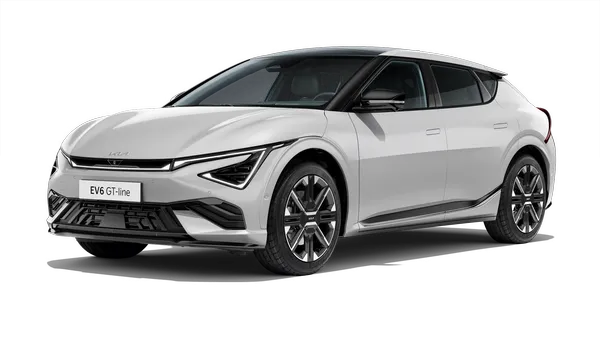
Contents
- Components and Components Location. Auto Defogging Actuator Description and Operation
- Auto Defogging Actuator Removal and Installation
- Auto Defogging Actuator Inspection
- Evaporator Core Removal and Installation
- Heater Unit Removal and Installation
- Mode Control Actuator Description and Operation
- Mode Control Actuator Removal and Installation
- Mode Control Actuator Inspection
- PTC Heater Description and Operation
- PTC Heater Removal and Installation
- PTC Heater Inspection
- Temperature Control Actuator Description and Operation
- Temperature Control Actuator Removal and Installation
- Temperature Control Actuator Inspection
Categories
- Manuals Home
- Kia EV6 Owners Manual
- Kia EV6 Service Manual
- Questions & Answers
- Video Guides
- Useful Resources
- New on site
- Most important about Kia EV6
- Privacy Policy

Copyright © 2026 Kia EV6 Manuals ⏱ 0.0272