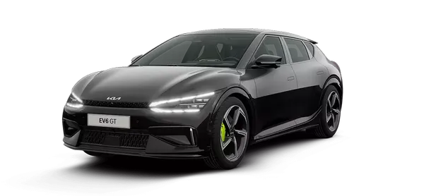
Kia EV6: Heating,Ventilation And Air Conditioning
Contents:
Single-Use Parts
Non-reusable parts (Single-Use Parts)
Workshop manual provides “Components and Components Location” which can be used to identify “Non-reusable parts”.
When repairing a vehicle, Non-reusable parts such as fasteners, gaskets, washers, clips and garnishes must be
replaced. Kia Non-reusable parts are designed to be installed only once.
Before working on a vehicle, check “Components and Components Location” to find the non-reusable parts in a
system.
※ Symbol of Non-reusable parts
Symbol
|
Meaning
|
|

|
Do not reuse the part. Replace with a new one.
|
※ Example of “Components and Components Location”

High Voltage Shut-off Procedures
High Voltage Shut-off Procedures
| High Voltage Shut-off Procedures |
|
•
|
When working on the high voltage system, the work should be performed by technicians who have
completed the relevant training. A lack of understanding of the high voltage system can lead to
serious accidents due to electric shock or short circuit.
|
|
•
|
When working on the high voltage system or related components, be sure to observe and be aware of
the "Safety Precautions, Cautions and Warnings". If not, it may cause serious accidents due
to electric shock or short circuit.
|
|
•
|
When working on high voltage system, make sure to check the Personal Protective Equipment (PPE) and
high voltage shut-off procedure.
|
|
|
High Voltage Component : Battery System Assembly (BSA), motor assembly, inverter assembly, high voltage
junction box, power cable, etc.
|
| 1. |
Check the Battery Management Unit (BMU) weld flag with the KDS.
(Data Analysis → Battery Management System (BMS) → BMU Weld Flag)
|
Refer to the KDS screen for operating conditions and details.
|
|
| 2. |
Open the front trunk (A).

|
| 3. |
Open the low voltage (12 V) battery service cover (A).

|
| 4. |
Turn the POWER OFF, separate the low voltage (12 V) battery ( - ) terminal (A).
Tightening torque :
7.8 - 9.8 N·m (0.8 - 1.0 kgf·m, 5.8 - 7.2 lb·ft)
|

|
| 5. |
Disconnect the service interlock connector (A).

|
•
|
Wait more than 5 minutes for capacitor of the high voltage battery system to be discharged
completely.
|
|
•
|
When working on a vehicle during discharging the capacitor, it can cause an electrical
shock or injury, so follow the manual.
|
|
|
The service interlock connector cannot be completely removed.

|
|
| 6. |
Remove the front under cover.
(Refer to Motor and Reduction Gear System - "Front Under
Cover")
|
| 7. |
Remove the high voltage battery cover (A).
Tightening torque :
7.8 - 11.8 N·m (0.8 - 1.2 kgf·m, 5.8 - 8.7 lb·ft)
|

|
| 8. |
Disconnect the front high voltage junction box power cable (A).

|
How to disconnect the connector
| 1) |
Release the locking clip (A) by pulling it.
|
| 2) |
Disconnect the connector by pushing the lever (A) in the direction of the arrow while
pressing the locking clip (B).
|

|
|
| 9. |
Remove the center floor rear under cover.
(Refer to Motor and Reduction Gear System - "Rear Under
Cover")
|
| 10. |
Disconnect the Integrated Charge Control Unit (ICCU) connector (A).

|
How to disconnect the connector
| 1) |
Release the locking clip (A) by pulling it.
|
| 2) |
Disconnect the connector while pressing the locking clip (B).

|
|
|
| 11. |
Disconnect the rear high voltage junction box power cable (A).

|
How to disconnect the connector
| 1) |
Release the locking clip (A) by pulling it.
|
| 2) |
Disconnect the connector by pushing the lever (A) in the direction of the arrow while
pressing the locking clip (B).
|
|
|
| 12. |
Measure the voltage between the high voltage power connector and high voltage battery terminal to check
whether the high voltage is shut-off.
30 V or less : Normal cut off high voltage circuit
Above 30 V : Fault on high voltage circuit
|
| (1)
|
Measure the voltage between the high voltage power connector positive ( + ) terminal and negative (
- ) terminal.

|
| (2)
|
Measure the voltage between the high voltage battery positive ( + ) and negative ( - ) terminal.

|
| (3)
|
Measure the voltage between the high voltage battery positive ( + ) terminal and ground.

|
| (4)
|
Measure the voltage between the high voltage battery negative ( - ) terminal and ground.

|
| (5)
|
Measure the voltage between the rear high voltage battery positive ( + ) and negative ( - )
terminal.

|
| (6)
|
Measure the voltage between the rear high voltage battery positive ( + ) terminal and ground.

|
| (7)
|
Measure the voltage between the rear high voltage battery negative ( - ) terminal and ground.

|
| 1) |
Check for insulation breakdown via KDS and physical leakage current before working on EV.
|
| 2) |
Remove the main fuse if insulation breakdown or leakage current is suspected. (Remove the
main fuse even when DTC CODE ON such as PRA malfunction)
(Refer to High Voltage Battery Control System - "Main
Fuse")
※ If there is no insulation breakdown or leakage current and it is normal, work without
removing the main fuse.
|
|
|
Description and Operation
| Description and Operation |
The heat pump system converts the flow of refrigerant to enable cooling/heating, minimizing battery consumption
during heating and improving the driving distance of the electric vehicle.
Cooling Mode Refrigerant Flow Sequence

| 1. |
An electric compressor compresses the refrigerant.
|
| 2. |
The compressed high-temperature, high-pressure refrigerant passes through the inner condenser. (there is no
heat exchange with the vehicle interior)
|
| 3. |
The compressed high-temperature, high-pressure refrigerant passes through the heat pump EXV without
expansion. (dehumidification EXV is closed)
|
| 4. |
The compressed high-temperature, high-pressure refrigerant transfers heat to the water-cooled condenser and
is condensed.
|
| 5. |
The refrigerant 3-way valve opens toward the outer condenser.
|
| 6. |
As the refrigerant passes through the outer condenser, it releases heat to the atmosphere and is further
condensed.
|
| 7. |
Refrigerant expansion in SOL & TXV (SOL open, high voltage battery chiller EXV closed)
|
| 8. |
The expanded, low-temperature, low-pressure refrigerant absorbs heat from the vehicle interior in the
evaporator.
|
| 9. |
The refrigerant that absorbs heat from inside the vehicle sends only gaseous refrigerant from the
accumulator to the electric compressor.
|
|
•
|
TXV : Thermal Expansion Valve
|
|
Battery-Only Cooling Mode

| 1. |
An electric compressor compresses the refrigerant.
|
| 2. |
The compressed high-temperature, high-pressure refrigerant passes through the inner condenser. (there is no
heat exchange with the vehicle interior)
|
| 3. |
The compressed high-temperature, high-pressure refrigerant passes through the heat pump EXV without
expansion. (dehumidification EXV is closed)
|
| 4. |
The compressed high-temperature, high-pressure refrigerant transfers heat to the water-cooled condenser and
is condensed.
|
| 5. |
The refrigerant 3-way valve opens toward the outer condenser.
|
| 6. |
As the refrigerant passes through the outer condenser, it releases heat to the atmosphere and is further
condensed.
|
| 7. |
Refrigerant expansion in battery chiller. (EXV duty control, SOL & TXV solenoid valve closed)
|
| 8. |
The battery chiller absorbs heat from the high voltage battery and the refrigerant expands
|
| 9. |
The refrigerant that absorbs heat from inside the vehicle sends only gaseous refrigerant from the
accumulator to the electric compressor.
|
|
•
|
TXV : Thermal Expansion Valve
|
|
Interior + Battery Cooling Mode

| 1. |
An electric compressor compresses the refrigerant.
|
| 2. |
The compressed high-temperature, high-pressure refrigerant passes through the inner condenser. (there is no
heat exchange with the vehicle interior)
|
| 3. |
The compressed high-temperature, high-pressure refrigerant passes through the heat pump EXV without
expansion. (dehumidification EXV is closed)
|
| 4. |
The compressed high-temperature, high-pressure refrigerant transfers heat to the water-cooled condenser and
is condensed.
|
| 5. |
The refrigerant 3-way valve opens toward the outer condenser.
|
| 6. |
As the refrigerant passes through the outer condenser, it releases heat to the atmosphere and is further
condensed.
|
| 7. |
Refrigerant expansion in SOL & TXV (solenoid valve open), Refrigerant expansion in battery chiller.
(EXV duty control)
|
| 8. |
The expanded low-temperature, low-pressure refrigerant absorbs heat from the vehicle interior in the
evaporator and absorbs heat from the battery coolant in the battery chiller.
|
| 9. |
The refrigerant that absorbs heat from inside the vehicle sends only gaseous refrigerant from the
accumulator to the electric compressor.
|
|
•
|
TXV : Thermal Expansion Valve
|
|
Heating Mode Refrigerant Flow Sequence

| 1. |
An electric compressor compresses the refrigerant.
|
| 2. |
When the compressed high-temperature and high-pressure refrigerant passes through the inner condenser, the
mix door opens to the heating side to dissipate heat.
|
| 3. |
The compressed high-temperature, high-pressure refrigerant works as an expansion valve through a small hole
in the heat pump EXV. (the dehumidification EXV is closed)
|
| 4. |
The expanded low-temperature and low-pressure refrigerant absorbs heat from the PE system in the
water-cooled condenser.
|
| 5. |
Refrigerant 3-way valve opens in the direction of bypassing the outer condenser to minimize heat loss in
the refrigerant.
|
| 6. |
Refrigerant that has absorbed heat from the drive (PE) system sends only gaseous refrigerant from the
accumulator to the electric compressor.
|
|
•
|
TXV : Thermal Expansion Valve
|
|
Heating & Dehumidification Mode

| 1. |
An electric compressor compresses the refrigerant.
|
| 2. |
When the compressed high-temperature and high-pressure refrigerant passes through the inner condenser, the
mix door opens to the heating side to dissipate heat.
|
| 3. |
The compressed high-temperature, high-pressure refrigerant works as an expansion valve through a small hole
in the heat pump EXV.
|
| 4. |
The dehumidification EXV opens and a portion of the expanded refrigerant passes through the evaporator to
remove moisture from the room air.
|
| 5. |
The expanded low-temperature and low-pressure refrigerant absorbs heat from the PE system in the
water-cooled condenser.
|
| 6. |
Refrigerant 3-way valve opens in the direction of bypassing the outer condenser to minimize heat loss in
the refrigerant.
|
| 7. |
Refrigerant that has absorbed heat from the drive PE system sends only gaseous refrigerant from the
accumulator to the electric compressor. (refrigerant that has been partially divided to dehumidify the indoor
air is recombined)
|
|
•
|
TXV : Thermal Expansion Valve
|
|
Troubleshooting
|
Before repairing the air conditioning components, check the refrigerant, compressor oil, air filter.
|
No Blower Operation
Suspected Causes
|
Repair
|
Faulty connection of connector
|
Check the connector
|
Heater fuse
|
Repair or replace
|
Blower relay
|
Repair or replace
|
Blower Motor
|
Repair or replace
|
Wiring break and short circuit
|
Repair or replace
|
No Air Temperature Control
Suspected Causes
|
Repair
|
Coolant amount
|
Repair or supplement
|
Faulty connection of connector
|
Check the connector
|
Temperature control actuator
|
Repair or replace
|
Auto temperature control unit
|
Repair or replace
|
No Electric A/C Compressor Operation
Suspected Causes
|
Repair
|
Refrigerant amount
|
Refrigerant charging / vacuum / leak test
|
A/C fuse
|
Repair or replace
|
Electric A/C compressor
|
Repair or replace
|
A/C pressure transducer
|
Repair or replace
|
A/C switch
|
Repair or replace
|
Evaporator temperature sensor
|
Repair or replace
|
Wiring break and short circuit
|
Repair or replace
|
Not Blowing Cold Air
Suspected Causes
|
Repair
|
Refrigerant amount
|
Refrigerant charging / vacuum / leak test
|
Refrigerant pressure
|
Refrigerant charging / vacuum / leak test
|
Electric A/C compressor
|
Repair or replace
|
A/C pressure transducer
|
Repair or replace
|
Evaporator temperature sensor
|
Repair or replace
|
A/C switch
|
Repair or replace
|
Auto temperature control unit
|
Repair or replace
|
Wiring break and short circuit
|
Repair or replace
|
Insufficient Cooling
Suspected Causes
|
Repair
|
Refrigerant amount
|
Refrigerant charging / vacuum / leak test
|
Electric A/C compressor
|
Repair or replace
|
Condenser
|
Repair or replace
|
Expansion valve
|
Repair or replace
|
Evaporator
|
Repair or replace
|
Refrigerant line
|
Repair or replace
|
A/C pressure transducer
|
Repair or replace
|
Auto temperature control unit
|
Repair or replace
|
Poor Air Inlet Control
Suspected Causes
|
Repair
|
Faulty connection of connector
|
Check the connector
|
Auto temperature control unit
|
Repair or replace
|
Intake actuator
|
Repair or replace
|
Wiring break and short circuit
|
Repair or replace
|
No Mode Control
Suspected Causes
|
Repair
|
Faulty connection of connector
|
Check the connector
|
Auto temperature control unit
|
Repair or replace
|
Mode control actuator
|
Repair or replace
|
Wiring break and short circuit
|
Repair or replace
|
No Cooling Fan Operation
Suspected Causes
|
Repair
|
Faulty connection of connector
|
Check the connector
|
Cooling fan fuse
|
Repair or replace
|
Fan motor
|
Repair or replace
|
VCU
|
Repair or replace
|
Wiring break and short circuit
|
Repair or replace
|
Other information:
Kia EV6 (CV/CV1A) 2022-2026 Workshop Manual: Blind-spot Collision-avoidance Assist (BCA) : (if equipped)
The Kia EV6 Blind-Spot Collision-Avoidance Assist (BCA) system is designed to help improve driving safety by
detecting vehicles approaching within the driver’s blind spot zones.
If the Kia EV6 detects a potential collision risk in the blind spot area, the system can warn the driver using
visual
indicators in the side mirrors, audible alerts, and steering wheel vibration warnings.
Kia EV6 (CV/CV1A) 2022-2026 Workshop Manual: Detection sensor
The front view camera of the Kia EV6 is used as the primary detection sensor for the High Beam Assist system.
The camera continuously monitors surrounding brightness, approaching vehicles, taillights, and road lighting
conditions while driving.
Please refer to the Detecting sensor(s) section for additional details regarding applicable sensors and
installation
locations.