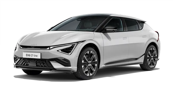
Kia EV6: Suspension System
Contents:
Single-Use Parts
Non-reusable parts (Single-Use Parts)
Workshop manual provides “Components and Components Location” which can be used to identify “Non-reusable parts”.
When repairing a vehicle, Non-reusable parts such as fasteners, gaskets, washers, clips and garnishes must be
replaced. Kia Non-reusable parts are designed to be installed only once.
Before working on a vehicle, check “Components and Components Location” to find the non-reusable parts in a
system.
※ Symbol of Non-reusable parts
Symbol
|
Meaning
|
|

|
Do not reuse the part. Replace with a new one.
|
※ Example of “Components and Components Location”

High Voltage Shut-off Procedures
High Voltage Shut-off Procedures
| High Voltage Shut-off Procedures |
|
•
|
When working on the high voltage system, the work should be performed by technicians who have
completed the relevant training. A lack of understanding of the high voltage system can lead to
serious accidents due to electric shock or short circuit.
|
|
•
|
When working on the high voltage system or related components, be sure to observe and be aware of
the "Safety Precautions, Cautions and Warnings". If not, it may cause serious accidents due
to electric shock or short circuit.
|
|
•
|
When working on high voltage system, make sure to check the Personal Protective Equipment (PPE) and
high voltage shut-off procedure.
|
|
|
High Voltage Component : Battery System Assembly (BSA), motor assembly, inverter assembly, high voltage
junction box, power cable, etc.
|
| 1. |
Check the Battery Management Unit (BMU) weld flag with the KDS.
(Data Analysis → Battery Management System (BMS) → BMU Weld Flag)
|
Refer to the KDS screen for operating conditions and details.
|
|
| 2. |
Open the front trunk (A).

|
| 3. |
Open the low voltage (12 V) battery service cover (A).

|
| 4. |
Turn the POWER OFF, separate the low voltage (12 V) battery ( - ) terminal (A).
Tightening torque :
7.8 - 9.8 N·m (0.8 - 1.0 kgf·m, 5.8 - 7.2 lb·ft)
|

|
| 5. |
Disconnect the service interlock connector (A).

|
•
|
Wait more than 5 minutes for capacitor of the high voltage battery system to be discharged
completely.
|
|
•
|
When working on a vehicle during discharging the capacitor, it can cause an electrical
shock or injury, so follow the manual.
|
|
|
The service interlock connector cannot be completely removed.

|
|
| 6. |
Remove the front under cover.
(Refer to Motor and Reduction Gear System - "Front Under
Cover")
|
| 7. |
Remove the high voltage battery cover (A).
Tightening torque :
7.8 - 11.8 N·m (0.8 - 1.2 kgf·m, 5.8 - 8.7 lb·ft)
|

|
| 8. |
Disconnect the front high voltage junction box power cable (A).

|
How to disconnect the connector
| 1) |
Release the locking clip (A) by pulling it.
|
| 2) |
Disconnect the connector by pushing the lever (A) in the direction of the arrow while
pressing the locking clip (B).
|

|
|
| 9. |
Remove the center floor rear under cover.
(Refer to Motor and Reduction Gear System - "Rear Under
Cover")
|
| 10. |
Disconnect the Integrated Charge Control Unit (ICCU) connector (A).

|
How to disconnect the connector
| 1) |
Release the locking clip (A) by pulling it.
|
| 2) |
Disconnect the connector while pressing the locking clip (B).

|
|
|
| 11. |
Disconnect the rear high voltage junction box power cable (A).

|
How to disconnect the connector
| 1) |
Release the locking clip (A) by pulling it.
|
| 2) |
Disconnect the connector by pushing the lever (A) in the direction of the arrow while
pressing the locking clip (B).
|
|
|
| 12. |
Measure the voltage between the high voltage power connector and high voltage battery terminal to check
whether the high voltage is shut-off.
30 V or less : Normal cut off high voltage circuit
Above 30 V : Fault on high voltage circuit
|
| (1)
|
Measure the voltage between the high voltage power connector positive ( + ) terminal and negative (
- ) terminal.

|
| (2)
|
Measure the voltage between the high voltage battery positive ( + ) and negative ( - ) terminal.

|
| (3)
|
Measure the voltage between the high voltage battery positive ( + ) terminal and ground.

|
| (4)
|
Measure the voltage between the high voltage battery negative ( - ) terminal and ground.

|
| (5)
|
Measure the voltage between the rear high voltage battery positive ( + ) and negative ( - )
terminal.

|
| (6)
|
Measure the voltage between the rear high voltage battery positive ( + ) terminal and ground.

|
| (7)
|
Measure the voltage between the rear high voltage battery negative ( - ) terminal and ground.

|
| 1) |
Check for insulation breakdown via KDS and physical leakage current before working on EV.
|
| 2) |
Remove the main fuse if insulation breakdown or leakage current is suspected. (Remove the
main fuse even when DTC CODE ON such as PRA malfunction)
(Refer to High Voltage Battery Control System - "Main
Fuse")
※ If there is no insulation breakdown or leakage current and it is normal, work without
removing the main fuse.
|
|
|
Tool Name / Number
|
Illustration
|
Description
|
Ball joint puller
09568 - 2J100
|

|
Used for removal of tie rod end
|
Lower arm ball joint remover
0K545 - A9100
|

|
Used for removal of front lower arm ball joint
|
Shock absorber lock nut remover.
0K546 - F6100
|

|
Used for removal or installing of front strut lock nut.
|
Shock absorber lock nut remover.
09546 - 3X100
|

|
Used for removal or installing of rear shock absorber lock nut.
|
Lower arm 'G' bushing replacement tool
09545 - AL100
|

|
Used for replacement of the lower arm 'G' bushing
|
Troubleshooting
| Heavy weight feeling on steering wheel |
Expected cause
|
Countermeasure
|
Faulty front wheel alignment
|
Adjust or repair
|
Over rotation resistance of lower arm ball joint
|
Replace
|
Over rotation resistance of strut bearing
|
Replace
|
Too low amount of tire air pressure
|
Adjust
|
| Steering wheel recovery trouble |
Expected cause
|
Countermeasure
|
Faulty front wheel alignment
|
Adjust or repair
|
| Noise or ride comfort trouble |
Expected cause
|
Countermeasure
|
Faulty wheel alignment
|
Adjust or repair
|
Inappropriated tire air pressure
|
Adjust
|
Faulty function of shock absorber
|
Replace
|
Damaged coil spring
|
Replace
|
Damaged stabilizer
|
Replace
|
Damaged lower arm bushing
|
Replace
|
Stabilizer link fixing nut got loose
|
Retighten
|
Damaged stabilizer link (dust cover tearing, ring broke away)
|
Replace
|
| Abnormal worned out of tire |
Expected cause
|
Countermeasure
|
Faulty wheel alignment
|
Adjust or repair
|
Inappropriated tire air pressure
|
Adjust
|
Expected cause
|
Countermeasure
|
Front wheel alignment trouble
|
Adjust or repair
|
Lower arm ball joint turning resistance is too small
|
Replace
|
Damaged lower arm bushing
|
Replace
|
| Vehicle pulls to one side |
Expected cause
|
Countermeasure
|
Wheel alignment trouble
|
Adjust or repair
|
Unbalance of right/left tire
|
Adjust or replace
|
Damaged or deformed lower arm bushing
|
Replace
|
Damaged coil spring
|
Replace
|
Expected cause
|
Countermeasure
|
Front wheel alignment trouble
|
Adjust or repair
|
Wheel balance trouble
|
Adjust or repair
|
Lower are ball joint turning resistance is too much or too small
|
Replace
|
Damaged stabilizer
|
Replace
|
Damaged lower arm bushing
|
Replace
|
Shock absorber operating trouble
|
Replace
|
Coil spring trouble
|
Replace
|
Under Body Parts Causing Abnormal Noise
Conditions for occurrence
|
Abnormal noise on uneven ground
|
Parts
|
Stabilizer bar link
|
Stabilizer bar bushing
|
Lower arm ball joint
|
Strut insulator
|
Trouble area
|

|

|

|

|
Type of abnormal noise
|
Rattling, Creaking noise
|
Squeaking noise
|
Clunking, Knocking noise
|
Clicking, Creaking noise
|
Occurring area
|
Under part
|
Under part
|
Under part
|
Upper part
|
Driving speed
|
20 - 40 ㎞/h (12.4 - 24.9 mph)
|
While low speed driving (20 - 40 ㎞/h (12.4 - 24.9 mph))
|
20 - 40 ㎞/h (12.4 - 24.9 mph)
|
-
|
Condition of road
|
Uneven road / bump
|
Uneven road / bump
|
Uneven road / bump
|
Uneven road / tough road
|
Reason
|
Loosen / leakage (teared down) / corrosion
|
Separation of bar and bushing / slip
|
Loosen / leakage (teared down) / corrosion
|
Tightened (decrease torque) and interference
|
Conditions for occurrence
|
Abnormal noise while going through uneven road / tough
road
|
Parts
|
Strut / Shock absorber
|
Strut / Shock absorber
|
Strut / Shock absorber
|
Strut / Shock absorber
|
Trouble area
|

|

|

|

|
Type of abnormal noise
|
Rubbing noise
|
Clicking, Creaking noise
|
Rubbing noise
|
Clicking noise
|
Occurring area
|
Upper part
|
Upper part
|
Upper part (rear)
|
Upper part (rear)
|
Driving speed
|
15 - 25 ㎞/h (9.3 - 15.5 mph)
|
15 - 25 ㎞/h (9.3 - 15.5 mph)
|
15 - 40 ㎞/h (9.3 - 24.9 mph)
|
30 - 50 ㎞/h (18.6 - 31.1 mph)
|
Condition of road
|
Uneven road
|
Uneven road
|
Uneven road and tough road
|
Tough road
|
Reason
|
Friction sound from piston load and bumper rubber inner side
|
Rolled down bumper rubber
(tapping sound of bumper rubber upper part and insulator under part)
|
Adhesion trouble of upper bracket rubber
|
Suspension tuning trouble
(damping force, rubber characteristic)
|
Conditions for occurrence
|
Abnormal noise on uneven road
|
Abnormal noise while steering
|
|
Parts
|
Lower arm "G" bushing
|
Cross member bushing
|
Strut bearing
|
Wheel / Hub bearing
|
Trouble area
|

|

|

|

|
Type of strange sound
|
Rubbing noise
|
Clicking noise
|
Clicking noise
|
Roaring noise
|
Occurring area
|
Under part
|
Under part
|
Upper part
|
Lower and side part
|
Driving speed
|
10 - 40 ㎞/h (6.2 - 24.9 mph)
|
-
|
-
|
20 - 60 ㎞/h (12.4 - 37.3 mph)
|
Condition of road
|
Bump / tough road
|
Even road
|
Even road
|
Even road
|
Reason
|
Dropped off / fallen off
|
Dropped off / fallen off
|
Grease leakage
|
Damaged from outer impact, foreign substance inflow
|
Wheel and tire diagnosis
Wheel /tire noise, vibration and harshness concerns are directly related to vehicle speed and are not generally
affected by acceleration, coasting or deceleration. Also, out-of-balance wheel and tires can vibrate at more than one
speed. A vibration that is affected by the engine rpm, or is eliminated by placing the transmission in Neutral is not
related to the tire and wheel. As a general rule, tire and wheel vibrations felt in the steering wheel are related to
the front tire and wheel assemblies. Vibrations felt in the seat or floor are related to the rear tire and wheel
assemblies. This can initially isolate a concern to the front or rear.
Careful attention must be paid to the tire and wheels. There are several symptoms that can be caused by damaged or
worn tire and wheel. Perform a careful visual inspection of the tires and wheel assemblies. Spin the tires slowly and
watch for signs of lateral or radial runout. Refer to the tire wear chart to determine the tire wear conditions and
actions
Wheel and tire diagnosis
|
Rapid wear at the center
|
Rapid wear at both shoulders
|
Wear at one shoulder
|
|

|

|

|
|
•
|
Center-tread down to fabric due to excessively over inflated tires
|
|
•
|
Excessive toe on drive wheels
|
|
•
|
Heavy acceleration on drive
|
|
|
•
|
Worn suspension components
|
|
•
|
Excessive cornering speeds
|
|
|
•
|
Toe adjustment out of specification
|
|
•
|
Camber out of specification
|
|
Partial wear
|
Feathered edge
|
Wear pattern
|
|

|

|

|
|
•
|
Damaged or worn brake discs
|
|
•
|
Sudden excessive braking
|
|
|
•
|
Toe adjustment out of specification
|
|
•
|
Damaged or worn tie rods
|
|
|
•
|
Toe adjustment out of specification
|
|
•
|
Damaged suspension component
|
|
Other information:
Kia EV6 (CV/CV1A) 2022-2026 Workshop Manual: Manual Speed Limit Assist (MSLA)
Speed Limit indicator
Displays the set speed
The Kia EV6 Manual Speed Limit Assist (MSLA) system allows the driver to set a maximum preferred driving speed
when
it is not desirable to exceed a certain speed limit.
If the Kia EV6 exceeds the preset speed limit, the Manual Speed Limit Assist system provides a warning by
flashing
the set speed indicator and sounding an audible chime until the vehicle speed returns within the selected limit.
Kia EV6 (CV/CV1A) 2022-2026 Workshop Manual: General Service Information
General Information
General Service Information
1.
Protect the vehicle's protective painted surfaces and internal parts with work covers (seat covers) or
tape (if damaged by tools) to prevent damage.
Before closing the hood, check the PE room for any tools or parts left.