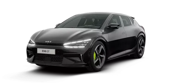
Kia EV6: Body (Interior / Exterior / Electrical) / Driver & Driving Assistance System
Contents:
Charging System Description and Operation
During POWER ON, battery voltage is supplied to the wireless power charger system to transmit an output of 5 W to
mobile phone.
Schematic Diagram

|
–
|
Wireless power charger (WPC) : Negligence of mobile phone, foreign object detection (FOD) decision.
|
|
–
|
Body domain control unit : Charging stops when LF (FOB key search) is driven
|
|
–
|
Wireless charging indicator : Displays the charging status.
|
|
–
|
Instrument cluster : Alerts about contact with mobile phone.
|
Wireless Power Charger system Major Functions
| 1. |
Charging Function
| (1)
|
Activation method
| a. |
Close all doors of the vehicle.
|
| b. |
Switch vehicle power to POWER ON.
|
| c. |
Place the wireless charging-enabled mobile phone on the tray.
|
|
| (2)
|
Charging status display
Mode
|
Charging LED display
|
Possible Cause
|
Stand-by for charging
|
LED turned OFF
|
-
|
Charging in process
|
Amber LED turned ON
|
-
|
Charging completed
|
Green LED turned ON
|
-
|
Charging error
|
Amber LED blinks
|
|
–
|
FOD detection : Blinks 10 times and pause for 50 sec → FOD status re-check.
|
|
–
|
High Temp : Blinks 10 times when not charged by high temperature. LED OFF till the
ERROR message is erased.
|
|
|
|
| 2. |
Mobile phone neglect alert function
| (1)
|
Activation method
| a. |
POWER OFF when the phone is still charging.
|
| b. |
Check if there is a phone on wireless charging unit.
|
| c. |
Display warning message on the cluster if the phone is left in the WPC charge pad and the
driver's door is opened or if the phone is left for more than 1 minute. (for about 4 ~ 5
seconds)
|
|

|
| 3. |
Overheating prevention
| (1)
|
Activation method
| a. |
If the thermistor temperature inside the wireless charging module rises above (158 °F (70
°C)), charging will stop to protect the mobile phone battery.
|
The amber LED of the charging display lamp blinks 10 times for 10 seconds.
|
|
| b. |
When the thermistor temperature drops below a certain temperature (149 °F (65 °C)) the
charging function is restarted.
|
When the charging function is restarted, the amber LED of the charging display lamp
will be turn on.
|
|
|
|
| 4. |
Foreign matter detection
| (1)
|
Charging will be disabled if there are coins or other metallic objects between the wireless
charging unit and the mobile phone.
|
Be careful as touching the foreign matter by hand as it may cause burns.
|
|
•
|
Foreign matter : All metallic objects such as coins, clips and precious metals.
|
|
•
|
The amber LED of the charging display lamp blinks 10 times for 10 seconds, and then
it is turned off for 50 seconds (total 60 seconds).
|
|
•
|
Do it twice (after 50 seconds off, check once and blink 10 times)
|
|
|
| (2)
|
If a foreign substance is detected and the charging of the mobile phone is stopped, the charging
resumes after about 60 seconds when the foreign substance is removed.
|
When the charging function is restarted, the amber LED of the charging display lamp will be
turn on.
|
|
|
| 5. |
Body domain control unit LF frequency interference prevention function
To avoid interference between the wireless charging frequency and the body domain control unit frequency
band.
| (1)
|
Wireless charging is stopped when the door is open or the body domain control unit is in LF
operation (smart key search).
e.g. Wireless charging function is stopped if the driver carries the smart key out of the vehicle
during IG ON.
|
Charging will stop and the amber LED of the charging display lamp will turn off.
|
|
| (2)
|
When the BDC unit LF operation is finished, it operates normally.
|
|
| 6. |
Turn the wireless charging function ON/OFF with User's Setting Menu (USM).

|
Wireless Power Charger (WPC) System Protection
Item
|
Condition
|
State
|
Protects against low/high voltage
|
Protects and stops charging under 8.5 V and over 16.5 V
|
LED OFF
(Stops operation)
|
Charges between 9 - 16 volts
|
Protects against reverse voltage
|
Protects and stops charging in case of reverse voltage
|
LED OFF
(Stops operation)
|
Protects against overcurrent
|
Protects and stops charging in case of detecting 4 amps
|
Amber LED blinks
|
Protects against overheating
|
Protects and stops charging in case of detecting 158 °F (70 °C) by internal temperature
sensor of wireless charging module
|
Amber LED blinks
|
Resumes under 149 °F (65°C)
|
Foreign substances
(Coins, clips, precious metals, etc.)
|
Protects and stops charging in case of detecting foreign matter (overheating
prevention)
|
Amber LED blinks
|
Prevents frequency interference
|
Protects and stops charging by activating IBU in case door or tailgate is open
|
LED OFF
(Stops operation)
|
Resumes in 3.5 seconds after all doors and tailgate are closed and IBU operation is
completed
|
Mobile phone neglect alert function
|
In case of smart phone on the charging pad when opening the door after POWER OFF.
|
Displays warning message on the instrument panel (for about 4 ~ 5 seconds)
|
Charging System On Vehicle Inspection
| 1. |
The wireless charging unit(WPC) can quickly diagnosed for problems with the KDS. (Refer to "DTC
guide")
| (1)
|
Self diagnosis : Inspect the Diagnostic Trouble Code (DTC) with the KDS.
(Refer to DTC guide when fault code is found.)
|
|
Refer to the KDS screen for operating conditions and details
|
|
Charging System Removal and Installation
|
•
|
When working on the high voltage system, the work should be performed by technicians who have
completed the relevant training. A lack of understanding of the high voltage system can lead to
serious accidents due to electric shock or short circuit.
|
|
•
|
When working on the high voltage system or related components, be sure to observe and be aware of
the "Safety Precautions, Cautions and Warnings". If not, it may cause serious accidents due
to electric shock or short circuit.
|
|
•
|
When working on the high voltage system, make sure to check the Personal Protective Equipment (PPE)
and high voltage shut-off procedure.
|
|
Wireless Power Charger (WPC)
| 1. |
Remove the wireless charging unit.
(Refer to Floor Console - "Floor Console Upper Cover")
|
Wireless Charging Indicator
| 1. |
Remove the floor console upper cover.
(Refer to Floor Console - "Floor Console Upper Cover")
|
| 2. |
Disconnect the connector (A).

|
| 3. |
Remove the wireless charging indicator (A) after removing the screws.


|
Vehicle to Load (V2L) Outlet
| 1. |
Remove the rear seat cushion assembly.
(Refer to Rear Seat - "Rear Seat Assembly")
|
| 2. |
Disconnect the Vehicle to Load (V2L) outlet connectors (A).

|
| 3. |
Remove the V2L outlet (A) after removing the nuts.

|
Front Console Cover USB Charger
| 1. |
Remove the front console cover.
(Refer to Floor Console - "Front Console Cover")
|
| 2. |
Remove the USB charger (A).


|
Clip position :

|
|
Floor Console USB Charger
| 1. |
Remove the floor console assembly.
(Refer to Floor Console - "Floor Console Assembly")
|
| 2. |
Disconnect the USB charger connector(A).

|
| 3. |
Remove the USB charger (A).

|
Front Seat Back Board USB Charger
| 1. |
Remove the front seat back board.
(Refer to Front Seat - "Front Seat Back Cover Assembly")
|
| 2. |
Separate the USB charger connector (A).

|
| 3. |
Remove the USB charger (A) after removing the screws.


|
|
•
|
When working on the high voltage system, the work should be performed by technicians who have
completed the relevant training. A lack of understanding of the high voltage system can lead to
serious accidents due to electric shock or short circuit.
|
|
•
|
When working on the high voltage system or related components, be sure to observe and be aware of
the "Safety Precautions, Cautions and Warnings". If not, it may cause serious accidents due
to electric shock or short circuit.
|
|
•
|
When working on the high voltage system, make sure to check the Personal Protective Equipment (PPE)
and high voltage shut-off procedure.
|
|
| 1. |
Install in the reverse order of removal.
|
| 2. |
Perform the Over The Air (OTA) controller S/W update with KDS when replacing the wireless charging unit.
(Refer to Security & Vehicle Ignition System - "Over The Air
(OTA)")
|
Head-Up Display (HUD) Description and Operation
Head-Up Display (HUD) System displays various information on the windshield glass which minimizes the driver’s eye
movement to enhance safety and convenience.
Information provided
| 1. |
Drive information : Vehicle speed, Drive mode
|
| 2. |
Turn by Turn navigation information, road signs, over speed.
|
| 3. |
Safety warning lamp : Smart Cruise Control (SCC), Lane Keeping Assist (LKA), Blind-Spot Collision Warning
(BCW)
|
Component Description
| 1. |
Head-Up Display (HUD) : Output various vehicle system information on windshield glass via CAN
communication.
|
| 2. |
Integrated monitor : Set ON/OFF through the User Setting Menu (USM).
|
| 3. |
Illumination sensor : It is equipped with bidirectional (A : vertical, B : horizontal) sensor. HUD
brightness is controlled depending on horizontal measurement (ambient brightness).

|
If illumination sensor measurement could not be detected, HUD will not be displayed. Check for
normal operation of illumination sensor before inspecting HUD.
|
|
| 4. |
Windshield glass : Windshield glass exclusive for Head-Up Display (HUD) is built in with double image
removal film.
|
When replacing the front windshield glass, a vehicle equipped with a head-up display (HUD) is
replaced with a dedicated windshield glass. Otherwise, head-up display (HUD) images may be overlapped
and displayed.
|
|
•
|
Use of window tinting film on windshield glass may decrease image quality.
|
|
•
|
Image may be distorted or seem dark if driver wears polarized sunglasses.
|
|
|
Head-Up Display (HUD) On Vehicle Inspection
| 1. |
The head-up display can quickly diagnosed for problems with the KDS. (Refer to "DTC guide")
| (1)
|
Self diagnosis : Inspect the Diagnostic Trouble Code (DTC) with the KDS.
(Refer to DTC guide when fault code is found.)
|
| (2)
|
S/W Management : Controlling other features including system option setting and zero point
adjustment.
(S/W Management → Head Up Display → HUD Calibration)
|
|
Refer to the KDS screen for operating conditions and details
|
|
Head-Up Display (HUD) Removal and Installation
|
•
|
When working on the high voltage system, the work should be performed by technicians who have
completed the relevant training. A lack of understanding of the high voltage system can lead to
serious accidents due to electric shock or short circuit.
|
|
•
|
When working on the high voltage system or related components, be sure to observe and be aware of
the "Safety Precautions, Cautions and Warnings". If not, it may cause serious accidents due
to electric shock or short circuit.
|
|
•
|
When working on the high voltage system, make sure to check the Personal Protective Equipment (PPE)
and high voltage shut-off procedure.
|
|
| 1. |
Remove the crash pad assembly.
(Refer to Crash Pad - "Crash Pad Assembly")
|
| 2. |
Separate the head up display (A) after disconnecting the head up display connectors (B).

|
| 3. |
Remove the head up display (A) after removing nut and screws.
Tightening torque :
6.9 - 10.8 N·m (0.7 - 1.1 kgf·m, 5.1 - 8.0 lb·ft)
|

|
|
•
|
When working on the high voltage system, the work should be performed by technicians who have
completed the relevant training. A lack of understanding of the high voltage system can lead to
serious accidents due to electric shock or short circuit.
|
|
•
|
When working on the high voltage system or related components, be sure to observe and be aware of
the "Safety Precautions, Cautions and Warnings". If not, it may cause serious accidents due
to electric shock or short circuit.
|
|
•
|
When working on the high voltage system, make sure to check the Personal Protective Equipment (PPE)
and high voltage shut-off procedure.
|
|
| 1. |
Install in the reverse order of removal.
|
| 2. |
Perform the order below with the KDS when replacing the head-up display.
(S/W Management → Head Up Display → HUD Calibration)
|
| 3. |
Perform Over The Air (OTA) controller S/W update with KDS.
(Refer to Security & Vehicle Ignition System - "Over The Air
(OTA)")
|
Multifunction Switch On Vehicle Inspection
| 1. |
The multifunction switch can quickly diagnosed for problems with the KDS. (Refer to "DTC guide")
| (1)
|
Self diagnosis : Inspect the Diagnostic Trouble Code (DTC) with the KDS.
(Refer to DTC guide when fault code is found.)
|
|
Refer to the KDS screen for operating conditions and details
|
|
Multifunction Switch Removal and Installation
|
•
|
When working on the high voltage system, the work should be performed by technicians who have
completed the relevant training. A lack of understanding of the high voltage system can lead to
serious accidents due to electric shock or short circuit.
|
|
•
|
When working on the high voltage system or related components, be sure to observe and be aware of
the "Safety Precautions, Cautions and Warnings". If not, it may cause serious accidents due
to electric shock or short circuit.
|
|
•
|
When working on the high voltage system, make sure to check the Personal Protective Equipment (PPE)
and high voltage shut-off procedure.
|
|
| 1. |
Remove the steering wheel.
(Refer to Steering System - "Steering Wheel")
|
| 2. |
Remove the steering column shroud panel.
(Refer to Crash Pad - "Steering Column Shroud Panel")
|
| 3. |
Disconnect the multifunction switch connectors (A).

|
| 4. |
Remove the multifunction switch (A) after removing the bolt.
Tightening torque :
4.4 - 6.4 N·m (0.45 - 0.65 kgf·m, 3.3 - 4.7 lb·ft, 39.1 - 56.4 lb·in)
|


|
|
•
|
When working on the high voltage system, the work should be performed by technicians who have
completed the relevant training. A lack of understanding of the high voltage system can lead to
serious accidents due to electric shock or short circuit.
|
|
•
|
When working on the high voltage system or related components, be sure to observe and be aware of
the "Safety Precautions, Cautions and Warnings". If not, it may cause serious accidents due
to electric shock or short circuit.
|
|
•
|
When working on high voltage system, make sure to check the Personal Protective Equipment (PPE) and
high voltage shut-off procedure.
|
|
| 1. |
Set the clock spring in a neutral position before installation.
Normal
|
Fault
|
|

|

|
|
If the clock spring is not set in neutral state, electric malfunctions such as airbag warning light
on, horn, hands-free, auto cruise, heated wiring and heated steering, and noise from turning the
steering may cause.
|
|
| 2. |
If the white cable is not visible in neutral indicator, perform the order below. (Manual setting for clock
spring neutral mode)
| (1)
|
Rotate the clock spring (A) clockwise until it stops after pressing the auto lock button (B).

|
| (2)
|
Rotate the clock spring (A) counterclockwise 3 times after pressing the auto lock button (B).

|
| (3)
|
Check the white cable in neutral indicator (A).

|
If the cable is visible in neutral indicator, it is neutral state.
|
|
|
| 3. |
Install in the reverse order of removal.
|
| 4. |
Check the airbag system and horn operate normally.
|
When the POWER ON, the airbag warning light should turns off after turning on for 3 - 6 seconds.
|
|
Virtual Engine Sound System (VESS) Description and Operation. Virtual Engine Sound System (VESS) On Vehicle Inspection
Virtual Engine Sound System (VESS) Description and Operation
The VESS makes a virtual engine sound during EV driving. As an EV produces no engine sound when driving, the VESS
produces sound to alert nearby pedestrians when the vehicle is moving at a speed of 0 to 28 km/h in R/N/D.
Virtual Engine Sound System (VESS) On Vehicle Inspection
| 1. |
The Virtual Engine Sound System (VESS) can quickly diagnosed for problems with the KDS. (Refer to "DTC
guide")
| (1)
|
Self diagnosis : Inspect the Diagnostic Trouble Code (DTC) with the KDS.
(Refer to DTC guide when fault code is found.)
|
|
Refer to the KDS screen for operating conditions and details
|
|
Virtual Engine Sound System (VESS) Removal and Installation
|
•
|
When working on the high voltage system, the work should be performed by technicians who have
completed the relevant training. A lack of understanding of the high voltage system can lead to
serious accidents due to electric shock or short circuit.
|
|
•
|
When working on the high voltage system or related components, be sure to observe and be aware of
the "Safety Precautions, Cautions and Warnings". If not, it may cause serious accidents due
to electric shock or short circuit.
|
|
•
|
When working on the high voltage system, make sure to check the Personal Protective Equipment (PPE)
and high voltage shut-off procedure.
|
|
| 1. |
Remove the front bumper assembly.
(Refer to Front & Rear Bumper - "Front Bumper
Assembly")
|
| 2. |
Disconnect the virtual engine sound unit & speaker (VESS) connector (A) and smart key antenna connector
(B).

|
| 3. |
Separate the wiring fixing clip (A).

|
Clip position :
|
|
| 4. |
Remove the unit (A) after removing the bolts.
Tightening torque :
7.8 - 11.8 N·m (0.8 - 1.2 kgf·m, 5.8 - 8.7 lb·ft)
|

|
|
•
|
When working on the high voltage system, the work should be performed by technicians who have
completed the relevant training. A lack of understanding of the high voltage system can lead to
serious accidents due to electric shock or short circuit.
|
|
•
|
When working on the high voltage system or related components, be sure to observe and be aware of
the "Safety Precautions, Cautions and Warnings". If not, it may cause serious accidents due
to electric shock or short circuit.
|
|
•
|
When working on the high voltage system, make sure to check the Personal Protective Equipment (PPE)
and high voltage shut-off procedure.
|
|
| 1. |
Install in the reverse order of removal.
|
| 2. |
Perform Over The Air (OTA) controller S/W update with KDS when replacing the virtual engine sound unit.
(Refer to Security & Vehicle Ignition System - "Over The Air
(OTA)")
|
Other information:
Kia EV6 (CV/CV1A) 2022-2026 Workshop Manual: 1. Manufacturer or Brand Identification
The tire sidewall of your Kia EV6 displays the name of the manufacturer or the tire brand. This information helps
identify the tire model and ensures that replacement tires meet the original equipment specifications
recommended
for the Kia EV6.
2. Maximum Permissible Inflation Pressure
This value indicates the highest air pressure that may safely be placed inside the tire.
Kia EV6 (CV/CV1A) 2022-2026 Workshop Manual: Front Motor and Reduction Gear Assembly Removal
Special Service Tool
Tool Name / Number
Illustration
Description
Engine fixture (adapter)09200 - 4X000
Used for anchoring the motor and reducer gear when removing and installing the motor and reducer gear
Removal
•
When working on high voltage system, the work should be performed by technicians who have completed
the relevant training.