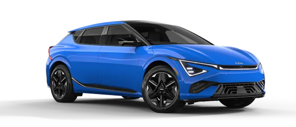
Kia EV6: Motor and Reduction Gear System
Contents:
Single-Use Parts
Non-reusable parts (Single-Use Parts)
Workshop manual provides “Components and Components Location” which can be used to identify “Non-reusable parts”.
When repairing a vehicle, Non-reusable parts such as fasteners, gaskets, washers, clips and garnishes must be
replaced. Kia Non-reusable parts are designed to be installed only once.
Before working on a vehicle, check “Components and Components Location” to find the non-reusable parts in a
system.
※ Symbol of Non-reusable parts
Symbol
|
Meaning
|
|

|
Do not reuse the part. Replace with a new one.
|
※ Example of “Components and Components Location”

High Voltage Shut-off Procedures
High Voltage Shut-off Procedures
| High Voltage Shut-off Procedures |
|
•
|
When working on the high voltage system, the work should be performed by technicians who have
completed the relevant training. A lack of understanding of the high voltage system can lead to
serious accidents due to electric shock or short circuit.
|
|
•
|
When working on the high voltage system or related components, be sure to observe and be aware of
the "Safety Precautions, Cautions and Warnings". If not, it may cause serious accidents due
to electric shock or short circuit.
|
|
•
|
When working on high voltage system, make sure to check the Personal Protective Equipment (PPE) and
high voltage shut-off procedure.
|
|
|
High Voltage Component : Battery System Assembly (BSA), motor assembly, inverter assembly, high voltage
junction box, power cable, etc.
|
| 1. |
Check the Battery Management Unit (BMU) weld flag with the KDS.
(Data Analysis → Battery Management System (BMS) → BMU Weld Flag)
|
Refer to the KDS screen for operating conditions and details.
|
|
| 2. |
Open the front trunk (A).

|
| 3. |
Open the low voltage (12 V) battery service cover (A).

|
| 4. |
Turn the POWER OFF, separate the low voltage (12 V) battery ( - ) terminal (A).
Tightening torque :
7.8 - 9.8 N·m (0.8 - 1.0 kgf·m, 5.8 - 7.2 lb·ft)
|

|
| 5. |
Disconnect the service interlock connector (A).

|
•
|
Wait more than 5 minutes for capacitor of the high voltage battery system to be discharged
completely.
|
|
•
|
When working on a vehicle during discharging the capacitor, it can cause an electrical
shock or injury, so follow the manual.
|
|
|
The service interlock connector cannot be completely removed.

|
|
| 6. |
Remove the front under cover.
(Refer to Motor and Reduction Gear System - "Front Under
Cover")
|
| 7. |
Remove the high voltage battery cover (A).
Tightening torque :
7.8 - 11.8 N·m (0.8 - 1.2 kgf·m, 5.8 - 8.7 lb·ft)
|

|
| 8. |
Disconnect the front high voltage junction box power cable (A).

|
How to disconnect the connector
| 1) |
Release the locking clip (A) by pulling it.
|
| 2) |
Disconnect the connector by pushing the lever (A) in the direction of the arrow while
pressing the locking clip (B).
|

|
|
| 9. |
Remove the center floor rear under cover.
(Refer to Motor and Reduction Gear System - "Rear Under
Cover")
|
| 10. |
Disconnect the Integrated Charge Control Unit (ICCU) connector (A).

|
How to disconnect the connector
| 1) |
Release the locking clip (A) by pulling it.
|
| 2) |
Disconnect the connector while pressing the locking clip (B).

|
|
|
| 11. |
Disconnect the rear high voltage junction box power cable (A).

|
How to disconnect the connector
| 1) |
Release the locking clip (A) by pulling it.
|
| 2) |
Disconnect the connector by pushing the lever (A) in the direction of the arrow while
pressing the locking clip (B).
|
|
|
| 12. |
Measure the voltage between the high voltage power connector and high voltage battery terminal to check
whether the high voltage is shut-off.
30 V or less : Normal cut off high voltage circuit
Above 30 V : Fault on high voltage circuit
|
| (1)
|
Measure the voltage between the high voltage power connector positive ( + ) terminal and negative (
- ) terminal.

|
| (2)
|
Measure the voltage between the high voltage battery positive ( + ) and negative ( - ) terminal.

|
| (3)
|
Measure the voltage between the high voltage battery positive ( + ) terminal and ground.

|
| (4)
|
Measure the voltage between the high voltage battery negative ( - ) terminal and ground.

|
| (5)
|
Measure the voltage between the rear high voltage battery positive ( + ) and negative ( - )
terminal.

|
| (6)
|
Measure the voltage between the rear high voltage battery positive ( + ) terminal and ground.

|
| (7)
|
Measure the voltage between the rear high voltage battery negative ( - ) terminal and ground.

|
| 1) |
Check for insulation breakdown via KDS and physical leakage current before working on EV.
|
| 2) |
Remove the main fuse if insulation breakdown or leakage current is suspected. (Remove the
main fuse even when DTC CODE ON such as PRA malfunction)
(Refer to High Voltage Battery Control System - "Main
Fuse")
※ If there is no insulation breakdown or leakage current and it is normal, work without
removing the main fuse.
|
|
|
Specification
Motor and Reduction Gear
Item
|
Specification
|
70 kW (Front wheel)
|
160 kW (Rear wheel)
|
Motor Type
|
Permanent magnet synchronous motor
(IPMSM)
|
Permanent magnet synchronous motor
(IPMSM)
|
Reduction gear ratio
|
10.65
|
10.65
|
Maximum power (kW)
|
70
|
160
|
Maximum torque (Nm)
|
255
|
350
|
Maximum rotational speed (rpm)
|
15,000
|
17,900
|
Cooling method
|
Oil cooling
|
Oil cooling
|
Oil Temperature Sensor
Item
|
Specification
|
Sensor Type
|
NTC thermistor
|
Operating Voltage (V)
|
4.75 - 5.25
|
Max current (mA)
|
100
|
Response time
|
Test medium : Coolant
|
MAX. 5 sec
|
Oil temperature [°C (°F)]
|
-40 to 150 (-40 to 302)
|
| Oil Temperature Sensor Table |
Temperature [°C (°F)]
|
Resistance (kΩ)
|
Minimum
|
Normal
|
Maximum
|
-40 (-40)
|
41.74
|
48.14
|
54.54
|
-30 (-22)
|
23.54
|
26.74
|
29.94
|
-20 (-4)
|
14.13
|
15.48
|
16.83
|
-10 (14)
|
8.393
|
9.308
|
10.223
|
0 (32)
|
5.281
|
5.790
|
6.299
|
10 (50)
|
3.422
|
3.714
|
4.007
|
20 (68)
|
2.310
|
2.450
|
2.590
|
30 (86)
|
1.554
|
1.658
|
1.762
|
40 (104)
|
1.084
|
1.148
|
1.212
|
50 (122)
|
0.7729
|
0.8126
|
0.8524
|
60 (140)
|
0.5615
|
0.5865
|
0.6115
|
70 (158)
|
0.4154
|
0.4311
|
0.4469
|
80 (176)
|
0.3122
|
0.3222
|
0.3322
|
90 (194)
|
0.2382
|
0.2446
|
0.2510
|
100 (212)
|
0.1844
|
0.1884
|
0.1924
|
110 (230)
|
0.1451
|
0.1471
|
0.1491
|
120 (248)
|
0.1139
|
0.1163
|
0.1187
|
130 (266)
|
0.0908
|
0.0930
|
0.0953
|
140 (284)
|
0.0731
|
0.0752
|
0.0773
|
150 (302)
|
0.0594
|
0.0614
|
0.0634
|
Tightening Torque
Item
|
N·m
|
kgf·m
|
lb·ft
|
lb·in
|
Front under cover bolts
|
7.8 - 11.8
|
0.8 - 1.2
|
5.8 - 8.7
|
-
|
Front rear under cover nuts
|
7.8 - 11.8
|
0.8 - 1.2
|
5.8 - 8.7
|
-
|
| Front Motor and Reduction Gear Mounting |
Item
|
N·m
|
kgf·m
|
lb·ft
|
lb·in
|
Motor mounting bracket bolt and nut
|
107.9 - 127.5
|
11.0 - 13.0
|
79.6 - 94.0
|
-
|
Motor mounting bracket bolts
|
63.7 - 83.4
|
6.5 - 8.5
|
47.0 - 61.5
|
-
|
| Front Motor and Reduction Gear Assembly |
Item
|
N·m
|
kgf·m
|
lb·ft
|
lb·in
|
Ground bolt
|
6.9 - 9.8
|
0.7 - 1.0
|
5.1 - 7.2
|
-
|
A/C pipe nut
|
8.8 - 13.7
|
0.9 - 1.4
|
6.5 - 10.1
|
-
|
Steering universal joint bolt
|
49.0 - 58.8
|
5.0 - 6.0
|
36.2 - 43.4
|
-
|
High voltage battery cover bolts
|
7.8 - 11.8
|
0.8 - 1.2
|
5.8 - 8.7
|
-
|
Stabilizer bar link nut
|
98.1 - 117.7
|
10.0 - 12.0
|
72.3 - 86.8
|
-
|
Front sub frame bolts and nut
|
107.9 - 127.5
|
11.0 - 13.0
|
79.6 - 94.0
|
-
|
Motor mounting bracket bolt and nut
|
107.9 - 127.5
|
11.0 - 13.0
|
79.6 - 94.0
|
-
|
Motor and reduction gear mounting bracket bolts
|
63.7 - 83.4
|
6.5 - 8.5
|
47.0 - 61.5
|
-
|
Item
|
N·m
|
kgf·m
|
lb·ft
|
lb·in
|
Center floor rear under cover nuts
|
3.9 - 5.9
|
0.4 - 0.6
|
2.9 - 4.3
|
34.7 - 52.1
|
Rear cross member under cover nuts
|
3.9 - 5.9
|
0.4 - 0.6
|
2.9 - 4.3
|
34.7 - 52.1
|
| Rear Motor and Reduction Gear Mounting |
Item
|
N·m
|
kgf·m
|
lb·ft
|
lb·in
|
Motor mounting bracket bolts
|
63.7 - 83.4
|
6.5 - 8.5
|
47.0 - 61.5
|
-
|
Motor mounting bracket bolt and nut
|
107.9 - 127.5
|
11.0 - 13.0
|
79.6 - 94.0
|
-
|
| Rear Motor and Reduction Gear Assembly |
Item
|
N·m
|
kgf·m
|
lb·ft
|
lb·in
|
Fast charge connector service cover nut
|
7.8 - 11.8
|
0.8 - 1.2
|
5.8 - 8.7
|
-
|
Fast charge connector bolt
|
9.8 - 10.8
|
1.0 - 1.1
|
7.2 - 8.0
|
-
|
Rear wheel speed sensor wiring bracket bolt
|
19.6 - 29.4
|
2.0 - 3.0
|
14.5 - 21.7
|
-
|
Ground bolt
|
7.8 - 11.8
|
0.8 - 1.2
|
5.8 - 8.7
|
-
|
High voltage cable bracket nut
|
9.8 - 11.8
|
1.0 - 1.2
|
7.2 - 8.7
|
-
|
Rear bumper under cover nuts
|
7.8 - 11.8
|
0.8 - 1.2
|
5.8 - 8.7
|
-
|
Under cover bracket bolts
|
49.0 - 58.8
|
5.0 - 6.0
|
36.2 - 43.4
|
-
|
Rear cross member bolt and nut
|
176.5 - 196.1
|
18.0 - 20.0
|
130.2 - 144.7
|
-
|
Ground bolt
|
6.9 - 10.8
|
0.7 - 1.1
|
5.1 - 8.0
|
-
|
Main Wiring Protector Bolts
|
6.9 - 9.8
|
0.7 - 1.0
|
5.1 - 7.2
|
-
|
High voltage cable bracket bolt
|
7.8 - 11.8
|
0.8 - 1.2
|
5.8 - 8.7
|
-
|
Rear motor and reduction gear nut
|
107.9 - 127.5
|
11.0 - 13.0
|
79.6 - 94.0
|
-
|
Rear motor and reduction gear bolt
|
63.7 - 83.4
|
6.5 - 8.5
|
47.0 - 61.5
|
-
|
176.5 - 196.1
|
18.0 - 20.0
|
130.2 - 144.7
|
-
|
Item
|
N·m
|
kgf·m
|
lb·ft
|
lb·in
|
Drain plug
|
44.1 - 58.8
|
4.5 - 6.0
|
32.5 - 43.4
|
-
|
Filler plug
|
44.1 - 58.8
|
4.5 - 6.0
|
32.5 - 43.4
|
-
|
Item
|
N·m
|
kgf·m
|
lb·ft
|
lb·in
|
Main wiring protector bolt
|
6.9 - 9.8
|
0.7 - 1.0
|
5.1 - 7.2
|
-
|
SBW actuator bolt
|
20.6 - 27.5
|
2.1 - 2.8
|
15.2 - 20.3
|
-
|
Item
|
N·m
|
kgf·m
|
lb·ft
|
lb·in
|
SBW control unit nut
|
9.8 - 11.8
|
1.0 - 1.2
|
7.2 - 8.7
|
-
|
Item
|
N·m
|
kgf·m
|
lb·ft
|
lb·in
|
Oil temperature sensor bolt
|
9.8 - 11.8
|
1.0 - 1.2
|
7.2 - 8.7
|
-
|
Item
|
N·m
|
kgf·m
|
lb·ft
|
lb·in
|
Electric Oil Pump (EOP) bolt
|
19.6 - 26.5
|
2.0 - 2.7
|
14.5 - 19.5
|
-
|
| Disconnect Actuator System (DAS) Motor |
Item
|
N·m
|
kgf·m
|
lb·ft
|
lb·in
|
Disconnect Actuator System (DAS) Motor bolts
|
4.9 - 5.9
|
0.5 - 0.6
|
3.6 - 4.3
|
43.4 - 52.1
|
Lubricant
Front motor and reduction gear [4WD]
Lubricant
|
Capacity
|
Kia genuine ATF SP4M-1
|
3.2 - 3.3 ℓ (0.85 - 0.87 U.S gal., 3.38 - 3.49 U.S.qt., 2.81 - 2.90 Imp.qt.)
|
Rear motor and reduction gear [2WD, 4WD]
Lubricant
|
Capacity
|
Kia genuine ATF SP4M-1
|
3.4 - 3.5 ℓ (0.90 - 0.92 U.S gal., 3.59 - 3.70 U.S.qt., 2.99 - 3.08 Imp.qt.)
|
Tool Name / Number
|
Illustration
|
Description
|
Reduction gear oil seal installer
09445 - GI100
|

|
Installation of the oil seal on the rear reduction gear case side[2WD]
Installation of the oil seal on the front reduction gear case and
housing[4WD]
(Used with the handle)
|
Reduction gear oil seal installer
09445 - GI200
|

|
Installation of the oil seal on the rear reduction gear case side[2WD]
(Used with the handle)
|
Handle
09231 - H1100
|

|
Used with the oil seal installer
|
Engine fixture (adapter)
09200 - 4X000
|

|
Used for anchoring the motor and reducer gear when removing and installing the motor and reducer gear
|
Description and Operation

|
•
|
Vehicle Control Unit (VCU) is the top-level controller of the vehicle that combines all the information to
meet the driver's needs.
|
|
•
|
VCU comprehensively controls Drive motor control, Air conditioning load control, 12 V electric load power
supply control, Disconnect Actuator System (DAS), and others.
|
Function
|
Detail
|
Drive Motor Control
|
|
•
|
Calculate usable battery power
|
|
•
|
Calculate usable motor toque
|
|
•
|
Order motor torque considering Driver demands (APS, Brake SW, Shift lever)
|
|
A/C Load Control
|
|
•
|
Order the final FATC permission power by using the battery information and FATC request power data.
|
|
12 V Electric Load Power Supply Control
|
|
•
|
LDC operation mode is determined according to 12 V battery information and vehicle status.
|
|
Disconnect Actuator System (DAS) Motor
|
|
•
|
As DAS is applied to 4WD vehicles, it controls the connection or disconnection between the front
wheel motor and drive shafts depending on the driving condition.
|
|
Cluster control
|
|
•
|
Command to indicate Drive Power, Energy Flow, Service lamp & various lamp lighting.
|
|
Distance to Empty (DTE)
|
|
•
|
Command to indicates usable battery energy and distance to empty based on prior drive pattern.
|
|
•
|
If drive path is set by using AVNT, DTE accuracy is improved by estimating the energy consumption
to destination.
|
|
Booking / Remote control
|
|
•
|
Remote control through a smartphone linked with Kia connect
|
|
•
|
Reservation Function through operation time setting by driver.
|
|
Regenerative braking control
|
|
•
|
Calculate motor charge torque command for regenerative braking.
|
|
•
|
Calculate regenerative brake force.
|
|
Contents
Categories



